Human-Computer Interaction 3e Dix, Finlay, Abowd, Beale
Note: This does not represent any real reactor although the sorts of problems it highlights do occur in real control rooms.
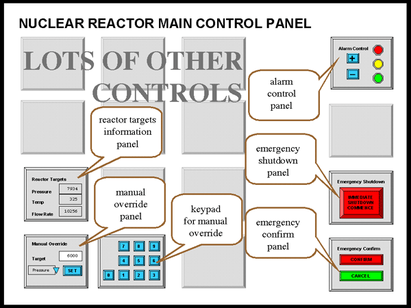
Figure 1 shows a sketch of the control panel of a nuclear power plant. The actual panel is very large covering the whole wall of the control room and contains many sub-panels and controls. The locations of some controls at the two ends of the panel are shown in figure CS.1, although it should be noted that the panel is much wider than the illustration.

Figure CS.1 - nuclear reactor main control panel
A few of the sub-panels are important for this case study:
Alarm Control panel
Emergency Shutdown panel
Emergency Confirm panel
Reactor Targets display
Manual Override panel
Numeric Keypad for the Manual Override panel
Details of the first three of these are shown in figure CS.2 and details of the last three in figure CS.3.
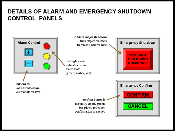
Figure CS.2 - alarm and emergency sub-panels
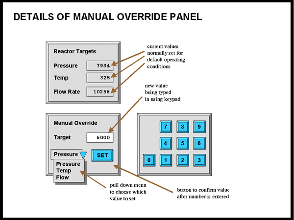
Figure CS.3 - reactor targets display and manual override
The system can be in one of three alarm states: GREEN, AMBER or RED.
(i) GREEN alarm state means everything is operating normally
(ii) AMBER alarm state is for when there is a minor problem with reactor operation. Workers in the reactor area are warned and take additional precautions, but no external services are involved.
(iii) RED alarm state is raised when the reactor is operating outside normal parameters and there is a possibility of external contamination. The police and other emergency services are alerted.
Typically AMBER state is raised once or twice a week and red state only a few times a year (so far only false alarms!). Raising a RED alarm unnecessarily causes significant inconvenience and cost both to the station staff and the external emergency services.
When the plant was commissioned, the alarm system controls worked as follows.
The current alarm state is indicated by which of the coloured lights on the Alarm Control panel is lit.. The '+' and '–' buttons on this panel increase or decrease the alarm state. Figure 4 shows a state transition network of the effects of the '+' and '–' buttons on the state as the system was initially installed.
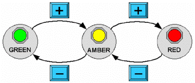
Figure CS.4 – STN for alarm state
When there is a very serious problem the operator can press the large red button labelled IMMEDIATE SHUTDOWN COMMENCE on the Emergency Shutdown panel, which initiates an emergency shutdown. This needs to be confirmed by pressing the CONFIRM button on the Emergency Confirm panel. (This is to prevent accidental shutdown of the plant.) The CONFIRM button is normally green, but glows red after the IMMEDIATE SHUTDOWN COMMENCE button has been pressed to remind the operator.
Emergency shutdown causes explosive bolts to blow that drive control rods into the reactor completely stopping the nuclear reaction. Restarting the reactor after emergency shutdown may take several weeks and costs many millions of pounds in lost production and replacement of parts damaged during the shutdown procedure.
The Reactor Targets panel shows the current target state of several reactor operating parameters. These are normally set by an automatic control system to values that ensure optimal energy production.
In an extreme emergency the operator may need to control these targets. The Manual Override panel allows this.
Manual override is only enabled in RED alarm state.
To override a particular target the operator selects the desired target (Pressure, Temperature or Flow Rate) from a dropdown menu, types in the desired value using a numeric keypad and then confirms the value using the SET button. (The SET button is necessary to prevent part-typed numbers being treated as the new value.)
Revised Alarm Control Operation
Some while after the plant was running a consultant suggested changing the operation of the Alarm Control panel and the software and hardware was revised in line with his recommendations. The current design works as follows.
Raising the alarm state from Green to Amber and back uses the '+' and '–' buttons as before. However now to raise the state from Amber to Red it is necessary to both press '+' and also confirm this by pressing the CONFIRM button on the Emergency Confirm panel.
Figure 5 shows the state transition network of the revised system.
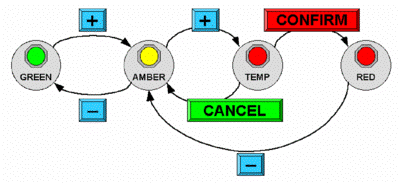
Figure CS.5 – STN for revised alarm state
Jenny, the Nuclear Power Plant operator has normal sight and no physical or perceptual impairments. Her shift started at 11pm and it is now 5am in the morning. So far the plant has been operating within normal parameters and the current alarm state is therefore green