S2.1 Introduction
In this chapter, we will discuss issues that arise during the implementation of an interactive system and the various tools and frameworks that support the programming of such systems. So far we have focused on the design and analysis of interactive systems from a relatively abstract perspective. We did this because it was not necessary to consider the specific details of the devices used in the interaction. Furthermore, consideration of that detail was an obstacle to understanding the interaction from the user's perspective. But we cannot forever ignore the specifics of the device. It is now time to devote some attention to understanding just how the task of coding the interactive application is structured.
Note that it is often the case that the job of specifying the behaviour of the interactive system falls to a different person than the role of actually coding it. However, even if you never expect to programme yourself, it is worth understanding some of the issues that occur when that specification is turned into running code.
The detailed specification gives the programmer instructions as to what the interactive application must do and the programmer must translate that into machine executable instructions to say how that will be achieved on the available hardware devices. The objective of the programmer then is to translate down to the level of the software that runs the hardware devices. At its crudest level, this software provides the ability to do things like read events from various input devices and write primitive graphics commands to a display. Whereas it is possible in that crude language to produce highly interactive systems, the job is very tedious and highly error prone; the user-interface developer does not normally want to think about the details of the electronics of the trackpad on a laptop computer or the optical sensors on a mouse. That is there is a need for levels of abstraction that lift the programming from the specific details of hardware to interaction techniques.
The programming support tools that we describe in this chapter aim to move this level of abstraction up from the raw sensors and low-level hardware devices to a higher level in which the programmer can code more directly in terms of the interaction objects of the application. The emphasis here is on allowing the programmer to build the system in terms of its desired interaction techniques, a term we use to indicate the intimate relationship between input and output. Though there is a fundamental separation between input and output devices in the hardware devices and at the lowest software level, the distinction can be removed at the programming level with the right abstractions and hiding of detail.
In the remainder of this chapter, we will address the various layers that constitute the move from the low-level hardware up to the more abstract programming concepts for interaction. We begin in Section 8.2 with the elements of a windowing system, which provide for device independence and resource sharing at the programming level. Programming in a window system frees the programmer from some of the worry about the input and output primitives of the machines the application will run on, and allows her to program the application under the assumption that it will receive a stream of event requests from the window manager. In Section 8.3 we describe the basic management of output and input. We consider the different ways in which the application interacts with the display mediated by the window manager and also at the two fundamental ways the stream of input events can be processed to link the interface with the application functionality. In Section 8.4, we describe the use of toolkits as mechanisms to link input and output at the programming level, allowing coding at the level of interaction objects rather than raw events and screen drawing. In Section 8.5, we discuss the architecture styles, frameworks and development tools that can help structure and guide the construction of a user interface. Section 8.6 looks at the issues that arise when developing for widely different platforms and devices, and techniques that help create code that can adapt to the different capabilities of different devices.
Isn't this just Software Engineering?
If you are a programmer, this might sound as if it is all just standard software engineering, simply applied to the user interface. Obviously HCI affects the design and therefore what is produced; however, the nature of user interfaces can make certain aspects of programming an interactive application more difficult then or at least different from other kinds of coding. That is, HCI also impacts how the design is put together.
One example is the separation between applications in a typical desktop environment. From a software engineering point of view it is important to keep them separate so that if the word processor crashes it does not bring down the web browser and vice versa. However, when the user looks at the screen it is all apparently available – just as in real life you may use your mug to hold open the page of a book, you don't think "mugs are functionally different from pages" you just do it. However, on the desktop even cut-and-paste or drag-and-drop between applications is effectively breaking the functional separation. Within a single application the same issue arises and users expect to be able to freely move between aspects of the user interface even if they belong to different modules of the underlying application.
S2.2 Windowing Systems
In earlier chapters, we have discussed the elements of the WIMP interface but only with respect to how they enhance the interaction with the end-user. Here we will describe more details of windowing systems used to build the WIMP interface. in particular we will describe the ways in which the window system provides:
device independence – hiding some of the differences between different IO devices
resource sharing – allowing multiple applications to use the same keybaord, screen, etc.
application management – swopping control between applications and various cross-application functions such as cut and paste
In order to achieve these things window managers have adapted several different kinds of internal architecture.
S2.2.1 Device independence
A computer may use many different kinds of pointing device (see also chapter 2): mouse, trackpad, joystick; it may even have a touchscreen such as an iPhone or iPad. Similarly there are various different kinds of keyboards from traditional QUERTY keyboards, to multi-tap phone keypads, and software-keyboards on touchscreens. Even 'standard' keyboards come in slightly different layouts in different countries and have more or less special keys such as cursor arrows, or function keys. Furthermore screens come in different resolutions from a few hundred pixels across on a phone to many thousands in a desktop 'cinema' display (Figure 8.1).
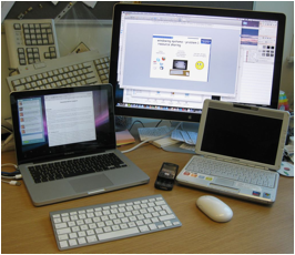
Figure 8.1. Devices differ: different keyboards, pointers and screens
As an application developer you often want to ignore these details as much as is sensible for the nature of the interaction. This abstraction is provided by a number of layers of software (Figure 8.2). These differ slightly in different platforms, but the typical layers are:
operating system – This provides the basic hardware interface, and low-level device drivers.
windowing system – This has a number of functions, but one is to provide abstractions such as an abstract idea of a pointer/mouse and an abstract screen/display model. The display model is often based on pixels, but there are alternatives such as the use of Postscript or vector graphics (see section 8.3.1).
toolkit (e.g. Java AWT/Swing) – These provide higher level abstractions such as components for menus, tabbed displays. Sometimes toolkits themselves come in several levels each adding more abstraction over the layer below.
The application will deal most with the highest level of toolkit (discussed in section 8.4), but typically can access the raw window manager or operating system when the toolkit does not provide everything that is needed. For example, the cut-and-paste support in Java AWT is limited, so for specialised applications you need to create small modules of native code to access the underlying window system clipboard. However, the more applications access underlying windowing systems or operating systems, the more code needs to be re-written when porting between platforms.
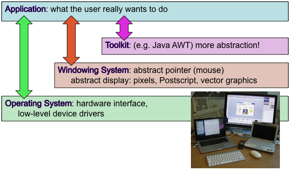
Figure 8.2. Layers between application and raw devices
S2.2.2 Resource sharing
Often you have many applications on a computer, but typically one screen, one keyboard and one mouse. Furthermore, the user has a single pair of eyes and fingers, so that even if you had a screen huge enough to show every possible application the user would not be able to look at them all at once! One job of the windowing system is to share these fixed interaction resources between applications. The windowing system manages this by largely separating out each application, so that for many purposes, each appears to have the computer with all its resources to itself. This is sometimes described as a virtual or abstract terminal (Figure 8.3). The window manager decides which keyboard and mouse events to pass on to each application (sometimes translating coordinates) and deals with overlapping or otherwise interfering windows, and each application reacts to mouse and keyboard events, and displays material on its windows, just as though there were no other applications.
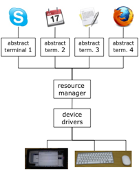
Figure 8.3. Giving each application an abstract terminal
The input devices are usually shared using the idea of input focus. By clicking on a window, or sometimes tabbing between them, the user can choose to use the keyboard to type into different applications, or the mouse to select or point in different windows. Note this is effectively time-based sharing as at any point in tome a single application 'owns' the keyboard and mouse.
For the screen there are several possibilities for window layout:
tiled (space shared) – Here each window/application is given a dedicated portion of the screen and can do what it likes there. This is often found in web sidebars, where widgets are stacked one above another. Note that this is a form of space-based sharing as each application has a part of the screen space. Of course, this has a natural limit when the screen is full. For web sidebars this is partly managed by the fact that the screen can scroll, however also each widget may be able to be hidden or expanded by clicking its title bar, thus giving the user more control over what is seen at any single moment.
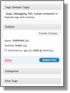
Figure 8.4. Tiled
sidebar with expandable widgets
in Wordpress admin screen
single app (time shared) – Some systems do the opposite and dedicate the whole screen to a single application or window, swopping which application gets the screen at any point in time. This was found in early versions of Windows, but is now more common in mobile devices such as phones as the screen is so small anyway that splitting it further would be silly. Note that this is a form of time-based sharing of the resource as at any moment precisely one application 'owns' the screen. The window system needs only have some means to swop between applications. For example, on the iPhone this is achieved by clicking the big button at the bottom and selecting an icon representing the intended application.
overlapping (time and space) – For desktop and laptop PCs, the most common layout is nether of the above, but instead the use of overlapping windows. In this case we have something that has elements of both time and space based sharing as some part of the screen have overlaps and are therefore time-shared (depending on which is on top) and other parts, where smaller windows sit side-by-side, are space shared.
 |  |  | ||
| (i) | (ii) | (iii) |
Figure 8.5. Window layout (i) tiled (ii) single app and (iii) overlapping
 Of
course it is not just the screen and keyboard that users care about; other aspects
of the device are also shared, especially when thinking about a mobile
device. There is one battery, so
that power management is crucial. Some phone-based operating systems work very like desktop-based ones
with applications running all the time and consequentially running down the
battery! The iPhone is often
criticised for being single-threaded,
but this is almost certainly one of the reasons for relatively long battery
life. The network is also a shared
resource and if one application hogs it may slow down others ... furthermore it
may cost the user in data charges!
Of
course it is not just the screen and keyboard that users care about; other aspects
of the device are also shared, especially when thinking about a mobile
device. There is one battery, so
that power management is crucial. Some phone-based operating systems work very like desktop-based ones
with applications running all the time and consequentially running down the
battery! The iPhone is often
criticised for being single-threaded,
but this is almost certainly one of the reasons for relatively long battery
life. The network is also a shared
resource and if one application hogs it may slow down others ... furthermore it
may cost the user in data charges!
S2.2.3 Application management
There are many applications! While they typically have control of what happens inside their windows, the window manager provides a consistent look-and-feel to the window 'decoration', the borders, resizing controls, title bar. As an application programmer you simply create a window and occasionally get events such as 'resized' or 'close', but otherwise the windowing system worries about what they look like and how they behave.
The window system also takes responsibility for many aspects of inter-application sharing such as cut & paste and drag & drop. As an application developer there are typically calls to the windowing systems to say "here is some data of this type for the clipboard", and the windowing system will provide events such as "data of this type has been dropped here". The window system also manages a degree of negotiation between the application providing data (where it was cut/copied or dragged from) and the application using it (paste or drop location). Some windowing systems also provide a level of scripting or automation between applications, for example the Mac Automator.
Finally, the windowing system has to provide some form of user interface to mange things like swopping between applications, closing windows, selecting the keyboard focus, or arranging overlapping windows and setting various global user preferences (e.g. Mac Finder, Windows Explorer). As well as 'big applications', even desktop interfaces now often have additional micro-applications such as the Mac Dashboard, which also need means for activating, etc.
S2.2.4 Architecture of window systems
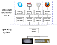
Bass and Coutaz [29] identify three possible architectures for the software to implement the roles of a windowing system. All of them assume that device drivers are separate from the application programs. They differ as to where they place the main window management role.
replicate in applications – The first option is to replicate the code for managing multiple processes within each of the separate applications (Figure 8.6.a). This is not a very satisfactory architecture because it forces each application to consider the difficult problems of resolving synchronization conflicts with the shared hardware devices. It also reduces the portability of the separate applications.
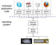
centralise in the OS kernel – The second option is to implement the management role within the kernel of the operating system, centralizing the management task by freeing it from the individual applications (Figure 8.6.b). Applications must still be developed with the specifics of the particular operating system in mind.
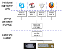
distribute in separate process (client–server) – The third option provides the most portability, as the management function is written as a separate application in its own right and so can provide an interface to other application programs that is generic across all operating systems (Figure 8.6.c). This final option is referred to as the client–server architecture, and has the added advantage that it can operate easily over networks.
(a) Replicated
(b) Centralised
(c) Client–server
Figure 8.6. Different window manager architectures
In practice, the divide among these proposed architectures is not so clear and any actual interactive application or set of applications operating within a window system may share features with any one of these three conceptual architectures.
The early versions of Mac OS and Windows assumed 'cooperative' applications', which, whilst not entirely replicated, did mean that each application was responsible for some window management functions. In the case of Mac OS X this allowed very efficient screen rendering, important for early graphics applications, albeit at the risk of freezing if an application failed.
Later versions of both Mac OS X and Windows follow more closely the centralised architecture, giving them far greater control over applications. However, whilst the programmer on both platforms sees the window manager and kernel as if they were one, in fact digging deeper the window manager is often separated out. Figure 8.7 shows a listing of the processes on a Mac OS X computer. The window manager (_windowserver) can clearly be seen as a separate process. That is there are some elements of client–server operation internally, even if not obvious to the user or programmer.
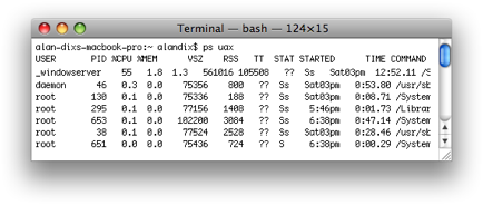
Figure 8.7. Mac OS X – window manager running as separate process
Even in a pure client–server window manager, there may be one component that is a separate application or process together with some built-in operating system support and hand-tuned application support to manage the shared resources. So applications built for a window system which is notionally based on the client–server model may not be as portable as one would think.
The classic example of a window system based on the client–server architecture is the industry-standard X Window System (Release 11), developed at the Massachusetts Institute of Technology (MIT) in the mid-1980s, and most familiar now on LINUX-based systems. Figure 8.8 shows the software architecture of X. X (or X11) is based on a pixel-based imaging model and assumes that there is some pointing mechanism available. What distinguishes X from other window systems, and the reason it has been adopted as a standard, is that X is based on a network protocol that clearly defines the server–client communication. The X Protocol can be implemented on different computers and operating systems, making X more device independent. It also means that client and server need not even be on the same system in order to communicate to the server. Each client of the X11 server is associated to an abstract terminal or main window. The X server performs the following tasks:
- allows (or denies) access to the display from multiple client applications;
- interprets requests from clients to perform screen operations or provide other information;
- demultiplexes the stream of physical input events from the user and passes them to the appropriate client;
- minimizes the traffic along the network by relieving the clients from having to keep track of certain display information, like fonts, in complex data structures that the clients can access by ID numbers.
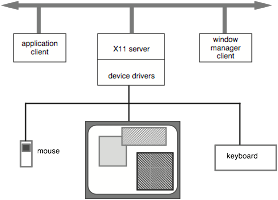
Figure 8.8 The X Window System (Release 11) architecture
A separate client – the window manager – enforces policies to resolve conflicting input and output requests to and from the other clients. There are several different window managers that can be used in X, and they adopt different policies. For example, the window manager would decide how the user can change the focus of his input from one application to another. One option is for the user to nominate one window as the active one to which all subsequent input is directed. The other option is for the active window to be implicitly nominated by the position of the pointing device. Whenever the pointer is in the display space of a window, all input is directed to it. Once the pointer is moved to a position inside another window, that window becomes active and receives subsequent input. Another example of window manager policy is whether visible screen images of the client windows can overlap or must be non-overlapping (called tiling). As with many other windowing systems, the client applications can define their own hierarchy of sub-windows, each of which is constrained to the coordinate space of the parent window. This subdivision of the main client window allows the programmer to manage the input and output for a single application similar to the window manager.
To aid in the design of specific window managers, the X Consortium has produced the Inter-Client Communication Conventions Manual (ICCCM), which provides conventions for various policy issues that are not included in the X definition. These policies include:
- rules for transferring data between clients;
- methods for selecting the active client for input focus;
- layout schemes for overlapping/tiled windows as screen regions.
S2.2.5 Not just the PC
Issues of application management and architecture are not just issues for PCs, but any platform where there are multiple applications:
phone – Faces similar issues to the PC sharing screen, keyboard, etc.. As noted the choice is usually to go for 'full screen' apps, not overlapping windows, however Vodafone 360 has semi-open apps, which take up several 'tile' locations in the screens showing application icons.
web – In web applications the browser in many ways takes to role of window manager. The browser may make use of he window system's ability to have several browser windows open, but within a window space is usually managed using tabs, which are effectively a form of space-based sharing.
web micro-apps – Various web platforms allow the user to add micro-applications such as Facebook apps and Google widgets. The platform may offer these access to shared data (e.g. Facebook friend's birthdays) and have to manage screen space, often using a combination of space-shared columns and time-shared tabs.
dedicated devices (e.g. microwave control panel) – These are mostly coded direct to hardware as they have very bespoke input and output. However, there are appliance-oriented variants of Java and Windows providing some higher-level abstractions.
S2.3 Programming the Application
S2.3.1 Paint models
When you want to put something on the screen it goes through all the layers referred to earlier. Your code interacts with a toolkit (say Jave AWT/Swing), which then passes this on to the window manager, which then manages things like overlaps with other application windows before interacting through the operating system and device drivers to actually paint pixels on the screen (see Figure 8.9).

Figure 8.9. Screen painting layers
Systems and toolkits differ in what you actually draw to:
direct to the screen – The simplest is when the application are given direct access to screen pixels. This is clearly most efficient for high-throughput graphics, such as vide replay, but has problems if the application misbehaves and starts to draw to areas of the screen that it shouldn't such as other applications' space or the windowing system's own UI elements.
direct to screen via viewport – The windowing system may exert a little more control by only allowing access through a 'viewport'. This means that when the application asks to draw pixels the output may be clipped if it is outside the allowed region, or if part of the window is currently covered by another window. This might also include coordinate transformations o that the application can effectively draw in a window with x and y coordinates 0-199, but have the window really positioned in the middle of the actual screen. For example, Java AWT works in this manner.
separate buffer – Sometimes instead of writing instantly to the screen the applications drawing operations are applied to a buffer in memory and only when this is finished is the whole buffer written to the screen. This may happen at the level of toolkit or and/or underlying window system and is normally called double buffering in a toolkit or retained bitmap in the windowing system. The latter we deal with later. The reason for double buffering at the toolkit level (whether or not the windowing system has a buffer), is to reduce flicker. Without double buffering it may be that the user sees a screen half-drawn, whereas double buffering means that the entire window instantly swops from the old to the new buffer. This is an option in Java Swing.
display list – Instead of working with the screen as an array of pixels, some systems store a list of operations recording, say, that there should be a line, image or text at a particular location on the screen. The toolkit then worries about showing these on the screen. This means that the application can simply change the display list when screen elements need to be updated, rather than redraw the whole screen. Also it allows the toolkit or window system to perform optimisations and hence is used in some high-performance graphical toolkits including OpenGL as well as older standards such as GKS (Graphics Kernel System) and PHIGS (Programmers Hierarchical Interface to Grahics).
page-description language – These are dedicated languages/notations used to describe the appearance of a page of graphics and text. The most commonly known are PDF and PostScript (both developed by Adobe Corporation). Both were originally developed for static printed pages, but have later been adapted for interactive displays (in NeXT and Mac OS X respectively). They model the screen as a collection of paths which serve as infinitely thin boundaries or stencils which can be filled in with various colors or textured patterns and images.
Buffering may also be used by the window system to store parts of the application window in order to more quickly update the screen when the user is swopping between overlapping windows. For example Mac OS X offers applications the choice of three levels of buffering which differ largely in how they cope with overlapping or translucent windows:
nonretained – This is the simplest options, the window manager remembers nothing and whenever a part of the application window that was hidden is later exposed the application is asked to redraw the previously hidden portion. This works best if the contents of the application window are changing very rapidly as any hidden parts will need to have fresh contents anyway.
retained – Where the window manager buffers just the hidden parts of overlapping windows. This means that when the window is later exposed the hidden part can be instantly drawn. Note that 'hidden' here includes being covered by a translucent overlay which may later move. (Note, this option was withdrawn in Mac OS 10.5, in favour of buffered below).
buffered – Here the window manager keeps a copy of the entire window, both hidden parts and non-hidden parts. This takes most memory, but gives the maximum responsiveness if, for example, the window is itself translucent and is dragged over other windows.
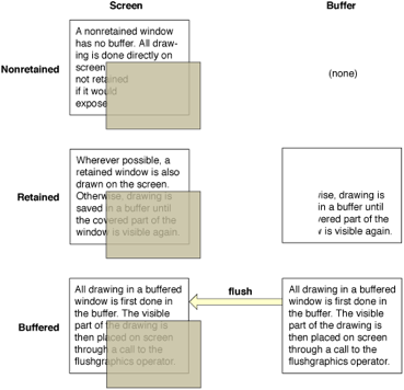
Fig 8.10. Buffering options in Mac OS X [Ap10]
There are different reasons why the screen needs to be redrawn:
internal events – Sometimes it is an event inside the application which leads to the needs to update the screen. For example, in a clock the digits need to change, or if downloading a large data file the progress indicator may need to update. In the case of internal events the application 'knows' that the screen has changed, but may need to tell the toolkit and ultimately the window manager.
external events – Alternatively the event may be due to something the user did to the application. For example the user might have clicked the 'bold' icon and the currently selected word needs to be emboldened. In this case it is the window manager that first 'knows' that the user ahs clicked the mouse, then passes this to the toolkit, which may sometimes respond directly (e.g. during navigation of a menu) or pass it on to the application.
However, just because the screen needs to be updated does not mean the update happens at that moment. For example, if there were many updates within a few tens of milliseconds, it would not be worth updating the screen several times as this would all be within a single display frame.
internal control – This is probably the easiest option to understand. When the application wants the screen changed it simply tells the toolkit/window manager that something needs to be updated. This has the problem noted above of potentially wasted updates, or taking time redrawing the screen when maybe user input is queued up needing to be processed. However this method works fine if there is some sort of intermediate representation such as the display list or a retained bitmap as then the actual display is only updated once per frame.
external control – In this case the toolkit / window manager decides when it wants a part of the screen to be updated (for example, when a hidden part is exposed) and asks the application to draw it. In Java this is what happens in a 'paint()' method. However, while this works easily for externally generated events when the window system 'knows' that a change is required, there is of course a problem for internally generated change. This is the purpose of the 'repaint()' method in Java; the application is saying to the toolkit "please repaint my window sometime when you are ready". At some later point, often when the input event queue is empty, the toolkit calls the applications 'paint()' method and screen is updated.
draw once per frame – This is a variant of external control used principally in video-game engines where much of the screen updates in each frame (e.g. first person shooters, or car racing). Once per frame the application is asked to redraw the screen. If event happen between these calls the application usually just updates some internal state but does not update the screen itself. Then when it is asked to redraw itself, the application takes the current state, maybe polls the state of joystick buttons, and generates the new screen.
S2.3.2 Event models
We now concentrate our attention on programming the actual interactive application, which would correspond to a client in the client–server architecture of Figure 8.6.c. Interactive applications are generally user driven in the sense that the action the application takes is determined by the input received from the user. We describe two programming paradigms that can be used to organize the flow of control within the application. The windowing system does not necessarily determine which of these two paradigms is to be followed.
The first programming paradigm is the read–evaluation loop, which is internal to the application program itself (see Figure 8.4). Programming on the Macintosh follows this paradigm. The server sends user inputs as structured events to the client application. As far as the server is concerned, the only importance of the event is the client to which it must be directed. The client application is programmed to read any event passed to it and determine all of the application-specific behavior that results as a response to it. The logical flow of the client application is indicated in the leftmost box of Figure 8.11. In pseudocode the read–evaluation loop would look like the following:
repeat
	read-event(myevent)
	case	myevent.type
		type_1 :
			do type_1 processing
		type_2 :
			do type_2 processing
		.
		.
		.
		type_n :
			do type_n processing
	end case
end repeat
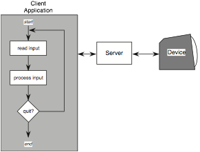
Figure 8.11 The read–evaluate loop paradigm
The application has complete control over the processing of events that it receives. The downside is that the programmer must execute this control over every possible event that the client will receive, which could prove a very cumbersome task. However, where this is the chosen method, suitable tools can greatly ease the process. For example, early Macintosh user interfaces were constructed in this way, but the MacApp framework automated many of the more tedious aspects.
The other programming paradigm is notification based, in which the main control loop for the event processing does not reside within the application. Instead, a centralized notifier receives events from the window system and filters them to the application program in a way declared by the program (see Figure 8.12). The application program informs the notifier what events are of interest to it, and for each event declares one of its own procedures as a callback (also called listener) before turning control over to the notifier. When the notifier receives an event from the window system, it sees if that event was identified by the application program and, if so, passes the event and control over to the callback procedure that was registered for the event. After processing, the callback procedure returns control to the notifier, either telling it to continue receiving events or requesting termination.
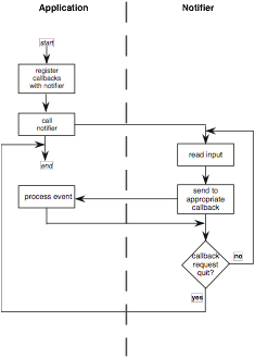
Figure 8.12 The notification-based programming paradigm
Figure 8.13 shows a fragment of pseudocode using the notification-based paradigm. In step (1) the application creates a menu and adds to options 'Save' and 'Quit'. Then at step (2) it tells the notifier to associate the callback function mySave with the 'Save' option and myQuit with the 'Quit' option. Later at (3) when the user selects the 'Save' option, the notifier calls the mySave method which would then do what is needed to save the current document, and when it returns the notifier goes on looking for more events to process. Later again (4) the user selects the 'Quit' menu option and the myQuit method is called. This would do any tidying up, perhaps close temporary files, but also (5) call some function on the notifier to tell it to stop processing. When it returns the notifier knows to stop and ends the program.
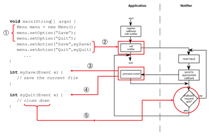
Figure 8.13 Fragment of pseudocode using notification paradigm
Control flow is centralized in the notifier, which relieves the application program of much of the tedium of processing every possible event passed to it by the window system. But this freedom from control does not come without a price. Suppose, for example, that the application program wanted to produce a pre-emptive dialog box, perhaps because it has detected an error and wants to obtain confirmation from the user before proceeding. The pre-emptive dialog effectively discards all subsequent user actions except for ones that it requires, say selection by the user inside a certain region of the screen. To do this in the read–evaluation paradigm is fairly straightforward. Suppose the error condition occurred during the processing of an event of type type_2. Once the error condition is recognized, the application then begins another read–evaluation loop contained within that branch of the case statement. Within that loop, all non-relevant events can be received and discarded. The pseudocode example given earlier would be modified in the following way:
repeat
    read-event(myevent)
    case   myevent.type
         type_1:
                do type_1 processing
         type_2:
                . . .
                if    (error-condition) then
                      repeat
                             read-event(myevent2)
                             case   myevent2.type
                                    type_1 :
                                    .
                                    .
                                    .
                                    type_n :
                             end case
                      until (end-condition2)
                end if
                . . .
         .
         .
         .
         type_n:
                do type_n processing
    end case
until (end-condition)
In the notification-based paradigm, such a pre-emptive dialog would not be so simple, because the control flow is out of the hands of the application programmer. The callback procedures would all have to be modified to recognize the situations in which the pre-emptive dialog is needed and in those situations disregard all events which are passed to them by the notifier. Things would be improved, however, if the application programmer could in such situations access the notifier directly to request that previously acceptable events be ignored until further notice.
Design Focus
Going with the grain
It is possible to use notification-based code to produce a pre-emptive interface dialog such as a modal dialog box, but much more difficult than with an event-loop-based system. Similarly, it is possible to write event-loop-based code that is not pre-emptive, but again it is difficult to do so. If you are not careful, systems built using notification-based code will have lots of non-modal dialog boxes and vice versa. Each programming paradigm has a grain, a tendency to push you towards certain kinds of interface.
If you know that the interface you require fits more closely to one paradigm or another then it is worth selecting the programming paradigm to make your life easier! Often, however, you do not have a choice. In this case you have to be very careful to decide what kind of interface dialog you want before you (or someone else) start coding. Where the desired interface fits the grain of the paradigm you don't have to worry. Where the desired behavior runs against the grain you must be careful, both in coding and testing as these are the areas where things will go wrong.
Of course, if you don't explicitly decide what behavior you want or you specify it unclearly, then it is likely that the resulting system will simply run with the grain, whether or not that makes a good interface.
S2.3.3 Putting it together – events in Java: what happens when you click?
We have seen that there are several different options for screen painting and event processing. We now work through the detailed steps that happen when an event is processed in the Java AWT/Swing user interface toolkit.
Underlying the way Java UIs work are two main kinds of activity, one responsible for processing events, such as mouse movement or keyboard input, and one for updating the screen, just as we have described in Section 8.3.1 and 8.3.2. In particular Java AWT/Swing adopts external control for screen painting and the notification-based paradigm for event management
We are going to pick up this story after listeners (callback) have been attached to events and go through the series of things that happen.
Most of your code to 'do things' will run as part of event processing, and if you use standard Swing components you may never directly write code that executes during screen painting … it is only when you need to produce a custom component and need to use direct graphics calls to draw lines, etc. that you may need to create a custom 'paint' method.
We'll go through the cycle of activities that typically occur when a user clicks the mouse. We will see the flow of between your own code and the parts of the Java API responsible for events and for screen painting. Figure 8.14 shows an overview of this process and we'll go through each step in detail.
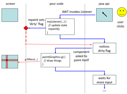
Figure 8.14 The event-paint cycle
Stage 1 – the user clicks
When the user presses or releases a mouse button, moves the mouse or types on the keyboard an event is generated deep in the system. At the operating system level this is first channelled to the right application depending on what windows are visible, which application has control of the keyboard etc.
Assuming this is your java application, this eventually ends up in the Java runtime environment, which does a similar job deciding which component the event should be directed to. It needs to take into account that components may be placed on top of one another (e.g. when a combo-box menu hides part of the panel beneath) or not be active (e.g. in tabbed panels).
Stage 2 – a listener is called
Having found out which component is to receive the event, the Java runtime looks up the relevant registered Listener for the event. So, if you have added a MouseListener then this will be found if the event is a mouse press/release or if the mouse is dragged into or out of the component. If no listener is found for the event a default behaviour is performed – sometimes to ignore it, sometimes to pass the event to the component containing the target (e.g. if the component has been added to a JPanel).
If you have registered a listener object for the event, then the appropriate method is called. In the case of a mouse click for a MouseListener object, the mouseClicked() method is invoked and your code starts to execute.
Stage 3 – doing your own things
Now your code gets to execute and this will typically mean updating some aspect of your internal state (or Model), setting variables, updating data structures etc. You may just be updating standard Swing components, perhaps setting putting a String into a JTextField – however this effectively updates the state of these components.
Note however, that your code inside the method is being run in the Java UI thread. This means that while it is executing no other user input can be processed (although events such as keypresses, mouse clicks etc. will be queued up to be dealt with later). This is quite a good thing – if this were not the case and a second user action happened before the first was complete you would have the second event being processed while the first was half way through – just imagine what would happen to your data structure!
Happily you are spared this problem, because there is a single UI thread all the events are serialised and the methods in your code to deal with them get executed one at a time in the right order.
However, there is a counter problem: if you do lots of computation in your event handlers, the user interface will freeze until you are done (haven't you see applications just like that!). Normally this is not an issue if you are just updating the odd variable etc. However, if you do really large amounts of computation (e.g. run a simulation), or need to access external resources (read a file, access a database, grab a web resource), then there is a danger that the interface may hang.
You can avoid a hung interface by launching your own thread to perform complex calculations, wait for network things to happen, etc. (see Section 8.3.4) – but if you do this then you need to be careful about synchronising this with the Java UI thread which manages events and screen painting … so let's assume the actions to perform are simple!
Stage 4 – calling repaint
Normally the effect of the event is to change something that requires the screen to be updated. If not why not? If something has been done then the user needs to know about it! (Recall the principle of observabilty and also "offer informative feedback" in Chapter 7) The possible exception would be where the event for some reason had no effect, perhaps clicking over an inactive button … in which case does the button clearly show it is inactive?
Assuming the screen does need to be updated, you may naturally feel you want your code to start writing to the screen: drawing lines, boxes, displaying text. However, in Java and many UI toolkits and environments you do not do this directly at this point. Instead, this is left to the screen painting activity. However, you do need to tell the runtime system that the screen requires updating and to do this you call the 'repaint()' method on components that need to be redrawn.
In the case where you are sub-classing a standard component (most likely JComponent or JPanel), this means you just run 'repaint()' and the repaint method of 'this' is called.
Note that the repaint() method does not actually repaint the screen! In fact all it does is set an internal 'screen dirty' flag that tells the Java runtime that the screen needs to be updated.
If you are using standard Swing components you may never call repaint() directly, but when, for example, you set the text in JTextField, internally the setText() method will call repaint(). Also if you use a Model-View-Controller model, you may again not call repaint() directly in your Listener, but it will update the Model, the Model will tell the View that it has changed and the View will call repaint()!
Note that when you update several components, repaint() will be called several times. The system underneath keeps track of this and builds a list of all the parts of the screen that need to be repainted. Also, if you are calling repaint() and only a small part of your component has changed, you can give it a bounding rectangle to tell it that only a part of it needs to be repainted; that is specify a rectangle that includes all areas of the screen that need to be repainted.
Stage 5 – UI waiting
Often repaint() is the last thing that happens in your listener, but need not be. However, when your listener has finished it returns. At this point the UI thread will catch up on any missed user events (if your listener did do lots of computation and took a long time!) calling the relevant listeners in order, but most often there are none and it simply waits for more user interaction.
Stage 6 – the paint thread enters the action
When there are no further user events queued events waiting, Java looks to see if the 'dirty' flag has been set and if so knows the screen needs updating.
Rather like with event management, it needs to work out which components need to be repainted and then asks each component to draw itself on screen by calling its paint() method. If there are several overlapping components it will draw them backmost first, so that the foremost component gets drawn on top.
Note that repainting may also occur when the events are internally generated, such as receiving a network message, or externally generated due to user actions that are not obviously to do with the application, such as resizing a window, or exposing it by closing another window.
Stage 7 – component paint thyself
Eventually your component gets to actually draw itself on screen. For standard Swing components this all happens in the Swing code, but if you want to do something special you can override the default paint method and write your own.
In the case of a simple component you can override paint() directly, but if you are creating a custom component that may contains other components (e.g. if you want a standard button on your custom component), then instead you may override paintComponent(). The default paint method calls this first to paint the background and then one by one calls the paint() method on its sub-components.
Your paint method is passed a Graphics object. This is effectively a 'handle' or way of accessing the portion of screen to paint to, although often is an off-screen buffer that is copied to the screen proper when you have finished.
The Graphics object can be drawn onto with lines, geometric shapes, text and images (there be dragons!).
The model while you are in paint() is of adding things one on top of another. If you draw some text and then draw a rectangle overlapping the text, the rectangle will cover the text (unless it is drawn in a translucent colour).
However, note that if you draw a rectangle on screen when paint is called one time and do not draw it when it is called again, the original rectangle will disappear – the model is that just before paint the relevant area of screen is wiped clean; you start with a blank canvas every time. This is why it important that you maintain a model of your internal state (whether this is a special class or just some variables), which you can refer to when painting the screen.
In most toolkits including Java AWT/Swing, anything you draw is clipped to the region the paint thread wants redrawn. This means you do not have to worry about drawing things near the edge of the screen that might draw outside its borders, or when your window is partially obscured.
However, when you have a very complex screen, you may want to use this fact and not bother to draw things that will fall outside the area being repainted. To do this you can look at the Graphics object and ask for its clipping region. However, you have to be careful to redraw everything that overlaps the region otherwise parts of things will disappear from screen. For even moderately complex screen layouts it is often easier to simply redraw everything.
… but do remember back-to-front drawing order.
Stage 8 – and so to rest
The paint() method returns. If the Graphics object was actually pointing to a temporary off-screen buffer, this is copied to the screen and the paint thread waits for the screen to be again marked dirty by repaint(), and the UI thread waits … all is peaceful in the world of the Java GUI … until the next user interaction!
S2.3.4 Doing several things at once: asynchrony and threads
The simplest kind of user interface proceeds as a turn-taking dialogue:
1. user does something
2. window system passes event to application
3. application does some processing of the event
4. application updates the screen
5. window system waits for next user action
Notice that the sequence of events in the Java AWT/Swing toolkit in the last section is a little more complicated. If the user actions produce many events (e.g. rapid typing or dragging the mouse), then it is possible for the simple turn-taking approach to get left behind. Occasionally this is evident in some applications that 'freeze' for a while and then produce a whole series of screen updates as they catch up on the users mouse clicks and keystrokes. To deal with this situation, Java only updates the screen when there are no more events waiting; that is it performs steps 2 and 3 repeatedly for each queued event and only does the screen update (step 4) when it has cleared the backlog.
This leads to a style of coding where the code for step 3 updates some part of the application state (e.g. appending a typed character to a document) and the code for step 4 updates the display based on the current state. We will see in the next section how this style of programming fits well the MVC architectural style.
This works very well for applications such as a word processor, where the screen just needs to show the current state of the document, but is slightly more complicated when some animation or transition is required.
One way to deal with this would be to have the state-update code set some sort of animation_required flag and then screen-update code be something like:
if animation_required flag is set
    for each frame of the animation
        set screen to the frame
        wait 40 milliseconds
clear animation_required flag
However, this could mean that if the user did anything else their input would be ignored until the animation was complete – if this was playing a video it could be a very long wait!
Happily many of the occasions you would need to do this, such as video replay, are likely to be handled by the toolkit or operating system by specialised functions. However, sometimes you need to do this yourself.
If so, to allow user input during the animation, user interface code instead sets a timer (say for 40 milliseconds) and registers a callback for the timer (just like the callback for a user event). The toolkit or window manager then generates a timer event every 40 milliseconds and the callback method is called. The application code in the callback then simply updates the current animation frame every time it gets a timer event.
Recall the 'draw once per frame' display update method described in section 8.3.1, which is used in some game engines. This is effectively an extreme variant of this where such timers drive all update, because the whole game is effectively one continuing and evolving animation.
Note that instead of your code being effectively dealing with one user action at a time and finishing with it, it is now dealing with potentially several things at the same time as at one moment it is updating an animation, the next dealing with a user keystroke, then returning to a bit more of the animation. That is there are several interleaved streams of activity going on at the same time. If, as in a game, the animation depends on things the user is doing (e.g. driving speed), then these interleaved streams of activity may interact.
As well as animations in the screen-update code, this form of interleaved coding can also happen in the state-update part of the user interface code, especially when some sort of network activity is required. In particular, this occurs in web interfaces that use AJAX (Asynchronous JavaScript and XML) [Ga05]. In an AJAX based system, the JavaScript code initiates a request for a web service, but typically does not wait for the reply. Instead it registers a callback, which gets called when the web service has returned a result (or maybe failed in some way).
For example, suppose you have web interface that displays the pages of an ebook. You might think of the code as follows:
current_page = 1;
next_page_button.click( process_next );  // set callback
function process_next() {
    current_page = current_ page + 1;
    page_content = << get text for current_page >>
    page_number_on_screen.setText( current_page );
    content_area_on_screen.setText( page_content );
}
If the full text of the book has been put in an array when the page was produced, the part of the code written "<< get text for page_num >>" may just be to access the array:
page_content = book_pages[ num ];
If so the style of the code fragment would work fine. However, this would only be likely to work with small books, and at some stage you may want to have the pages retrieved from the server using AJAX. Now the code that seemed to all be one gets split in two:
current_page = 1;
next_page_button.click( async_process_next );  // set callback
function async_process_next() // assume attached to the 'load' button
{
    current_page = current_page + 1;
    request_uri = "http://ex.com/api/page/" + current_page;
    // register callback and initiate request
    start_AJAX_request( request_uri, finish_process_next );
}
function finish_process_next( response ) {
    page_content = response.getTextContent();
    page_number_on_screen.setText( current_page );
    content_area_on_screen.setText( page_content );
}
Again you need to be very careful in such applications. First you need to be careful because, as above, you have to split code that in your mind belongs together into several pieces broken by the AJAX calls. Second you have to be careful as the user may perform fresh actions, invoking more of your event callbacks, before the web service response is received.
Figure 8.15 shows a possible timeline of the code above. The user presses the 'next' button twice in close succession. Initially the current page is 41. The application updates this to 42 and then initiates an AJAX request for page 42. However, before this call returns the user's second 'next' button press is processed, so the page number is updated to 43 and a second AJAX request initiated. So, when the response to the first request is received, the page number says 43 even though the page that gets displayed is page 42.
After a while the second request would return, page 43 contents would be displayed and things would be consistent again, but in the mean time the display would be very confusing.
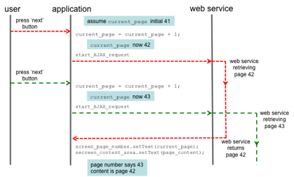
Figure 8.15 Possible timeline of asynchronous code
Even worse, if the AJAX request for page 43 returned more quickly than the first request, the system might first display page 43 and then a few moments later display page 42 when the first request completes. This time the screen would never become consistent and continue to show page 42 with the page number saying 43. To confuse the user more, if the user then presses next again, the page number would move on toe page 44 and page 44 would be displayed, missing page 43 entirely.
This sort of situation can be avoided with careful coding. In particular, you can usually associate additional information with an AJAX call, so that when you receive the response you know precisely which request it corresponds to. However, care is still required to avoid creating inconsistent or buggy results.
When you test your code the web service is often local or on a fast connection, so that you never experience this interleaving of user actions with the send and receive of the web service call. It is only, when your code is deployed and running on a slower connection, or where the web server is heavily loaded, that this interleaving occurs and your code breaks! Similar issues occur for multi-user code and will be discussed in Chapter 20.
Even if all animations and network access is managed through asynchronous callbacks, still the application may need to perform some very complex and time-consuming calculation or process a very large data file. So, the user interface could still freeze while this happens. When there are potential delays like this, you should display a progress indicator, but even doing this is a problem. Going back to the five steps at the beginning of this section; step 4 (screen update) would not happen until step 3 (state update) is completed, so the progress indicator would not appear until the work was complete!
One way to deal with this is to split you complex calculation into lots of small chunks (e.g. reading a few hundred lines of the big file per chunk). At the end of each chunk you set a timer for a very short time (maybe one millisecond). If there are no other events queued you just run straight away, but if there are they get a chance to be processed. If the code is simple (albeit long!) loop, then splitting the code is usually straightforward. However, if the code has loops within loops, or many embedded levels of function calls, things can be more complicated and you end up 'inverting' the code turning the implicit state of loop variables and the call stack into explicit state that you manage yourself. If the code you are using is in third-party libraries, then you cannot break these down at all.
Some platforms have a special system call such as yield() which means "if you want to process some other events do it now", which solves the inversion problems, but not that of third-party libraries.
An alternative, which is available in Java and many other platforms (but not most JavaScript) is threads. This means that several pieces of code can run effectively at the same time, or even the same piece of code may be executing twice concurrently! When a user event requires a lot of work (perhaps reading the large file), a separate thread is created and the complex calculation is performed in this thread. The event processing method can then return and the normal user interface thread keep on processing new user events while the calculation thread proceeds at the same time.
Threads take away the problem of needing to invert code, but are themselves complicated when you want to pass information back and forth between the thread and the main UI code. If both threads try to update the same data things can get very nasty! Even if the UI thread just reads a data structure produced by the calculation thread (e.g. the progress per cent) it may be possible to read a partially written and inconsistent state. These problems can be dealt with if you are careful, but do require a different manner of thinking.
When producing applications, it is also easy to assume that this sort of delay can only occur when there is some obvious slow processing such as using a web service or very complex calculations. However, files may sit on network drives, so even reading a small file may occasionally take a long time (or a long time to fail) if there is some sort of network glitch. This is one of the reasons many programs occasionally hang for a short period and then continue as normal. So as you design interactive applications, whether in web or desktop, you need to be aware that these delays can happen and perhaps expect asynchrony to be the norm rather than the exception.
S2.4 Toolkits and widgets
As we discussed in Chapter 4, a key feature of WIMP interfaces from the user's perspective is that input and output behaviors are intrinsically linked to independent entities on the display screen. This creates the illusion that the entities on the screen are the objects of interest – interaction objects we have called them – and that is necessary for the action world of a direct manipulation interface. A classic example is the mouse as a pointing device. The input coming from the hardware device is separate from the output of the mouse cursor on the display screen. However, since the visual movement of the screen cursor is linked with the physical movement of the mouse device, the user feels as if he is actually moving the visual cursor. Even though input and output are actually separate, the illusion causes the user to treat them as one; indeed, both the visual cursor and the physical device are referred to simply as 'the mouse'. In situations where this link is broken, it is easy to see the user's frustration.
In Figure 8.16, we show an example of how input and output are combined for interaction with a button object. As the user moves the mouse cursor over the button, it changes to a finger to suggest that the user can push it. Pressing the mouse button down causes the button to be highlighted and might even make an audible click like the keys on some keyboards, providing immediate feedback that the button has been pushed. Releasing the mouse button unhighlights the button and moving the mouse off the button changes the cursor to its initial shape, indicating that the user is no longer over the active area of the button.
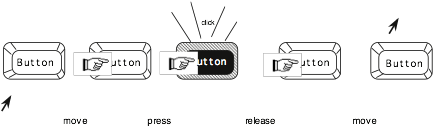
Figure 8.16 Example of behavior of a button interaction object
From the programmer's perspective, even at the level of a windowing system, input and output are still quite separate for everything except the mouse, and it takes quite a bit of effort in the application program to create the illusion of the interaction object such as the button we have just described. To aid the programmer in fusing input and output behaviors, another level of abstraction is placed on top of the window system – the toolkit. A toolkit provides the programmer with a set of ready-made interaction objects – alternatively called interaction techniques, gadgets or widgets – which she can use to create her application programs. The interaction objects have a predefined behavior, such as that described for the button, that comes for free without any further programming effort. In particular, many of the issues to do with state and display update described in the previous section get managed by the individual interaction objects, so that you, for example, just set the contents of a text widget and it worries about actually drawing the characters on the screen.
Toolkits exist for all windowing environments (for example, OSF/Motif and XView for the X Window system, the Macintosh Toolbox and the Software Development Toolkit for Microsoft Windows). In addition many programming languages provide another level of platform-independent toolkit (e.g. Java AWT/Swing) which allows programmers to create code to run on many different systems.
To provide flexibility, the interaction objects can be tailored to the specific situation in which they are invoked by the programmer. For example, the label on the button could be a parameter, which the programmer can set when a particular button is created. More complex interaction objects can be built up from smaller, simpler ones. Ultimately, the entire application can be viewed as a collection of interaction objects whose combined behavior describes the semantics of the whole application.
1.	/*
2.	 * quit.c -- simple program to display a panel button that says "Quit".
3.	 * Selecting the panel button exits the program.
4.	 */
5.	# include <xview/xview.h>
6.	# include <xview/frame.h>
7.	# include <xview/panel.h>
8.	Frame frame;
9.	main  (argc, argv)
10.	int argc;
11.	char *argv[];
12.	{
13.		Panel panel;
14.		void quit();
15.
16.		xv_init(XV_INIT_ARGC_PTR_ARGV, &argc, argv, NULL);
17.		frame = (Frame) xv_create(NULL, FRAME,
18.						FRAME_LABEL,	argv[0],
19.						XV_WIDTH,	200,
20.						XV_HEIGHT,	100,
21.						NULL);
22.		panel = (Panel) xv_create(frame, PANEL, NULL);
23.		(void) xv_create(panel, PANEL_BUTTON,
24.						PANEL_LABEL_STRING,	"Quit",
25.						PANEL_NOTIFY_PROC,	 quit,
26.						NULL);
27.		xv_main_loop(frame);
28.		exit(0);
29.	}
30.	void quit()
31.	{
32.		xv_destroy_safe(frame);
33.	}
Figure 8.17 A simple program to demonstrate notification-based programming. Example taken from Dan Heller [169], reproduced by permission of O'Reilly and Associates, Inc
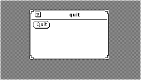
Figure 8.18 Screen image produced by sample program quit.c
The sample program quit.c in Figure 8.17 uses the XView toolkit, which adopts the notification-based programming paradigm as described in Section 8.3.2. The program produces a window, or frame, with one button, labelled 'Quit', which when selected by the pointer device causes the program to quit, destroying the window (see Figure 8.18 for the screen image it produces). Three objects are created in this program: the outermost frame, a panel within that frame and the button in the panel (a PANEL_BUTTON interaction object). The procedure xv_create, used on lines 17, 22 and 23 in the source code of Figure 8.17, is used by the application program to register the objects with the XView notifier. In the last instance on line 23, the application programmer informs the notifier of the callback procedure to be invoked (the PANEL_NOTIFY_PROC) when the object, a button, is selected. The application program then initiates the notifier by the procedure call xv_main_loop. When the notifier receives a select event for the button, control is passed to the procedure quit, which destroys the outermost frame and requests termination.
The code describes what elements are required on screen and what to do when the 'Quit' button is pressed. However, it does not need to worry about the detailed interaction with the button in Figure 8.16. The button interaction object in the toolkit already has defined what actual user action is classified as the selection event, so the programmer need not worry about that when creating an instance of the button. The programmer can think of the event at a higher level of abstraction, that is as a selection event instead of as a release of the left mouse button.
In Chapter 7 we discussed the benefits of consistency and generalizability for an interactive system. One of the advantages of programming with toolkits is that they can enforce consistency in both input form and output form by providing similar behavior to a collection of widgets. For example, every button interaction object, within the same application program or between different ones, by default could have a behavior like the one described in Figure 8.8. All that is required is that the developers for the different applications use the same toolkit. This consistency of behavior for interaction objects is referred to as the look and feel of the toolkit. Style guides, which were described in the discussion on guidelines in Chapter 7, give additional hints to a programmer on how to preserve the look and feel of a given toolkit beyond that which is enforced by the default definition of the interaction objects.
Two features of interaction objects and toolkits make them amenable to an object-oriented approach to programming. First, they depend on being able to define a class of interaction objects, which can then be invoked (or instantiated) many times within one application with only minor modifications to each instance. Secondly, building complex interaction objects is made easier by building up their definition based on existing simpler interaction objects. These notions of instantiation and inheritance are cornerstones of object-oriented programming. Classes are defined as templates for interaction objects. When an interaction object is created, it is declared as an instance of some predefined class. So, in the example quit.c program, frame is declared as an instance of the class FRAME (line 17), panel is declared as an instance of the class PANEL (line 22) and the button (no name) is declared as an instance of the class PANEL_BUTTON (line 23). Typically, a class template will provide default values for various attributes. Some of those attributes can be altered in any one instance; they are sometimes distinguished as instance attributes.
In defining the classes of interaction objects themselves, new classes can be built which inherit features of one or other classes. In the simplest case, there is a strict class hierarchy in which each class inherits features of only one other class, its parent class. This simple form of inheritance is called single inheritance and is exhibited in the XView toolkit standard hierarchy for the window class in Figure 8.19. A more complicated class hierarchy would permit defining new classes that inherit from more than one parent class – called multiple inheritance.
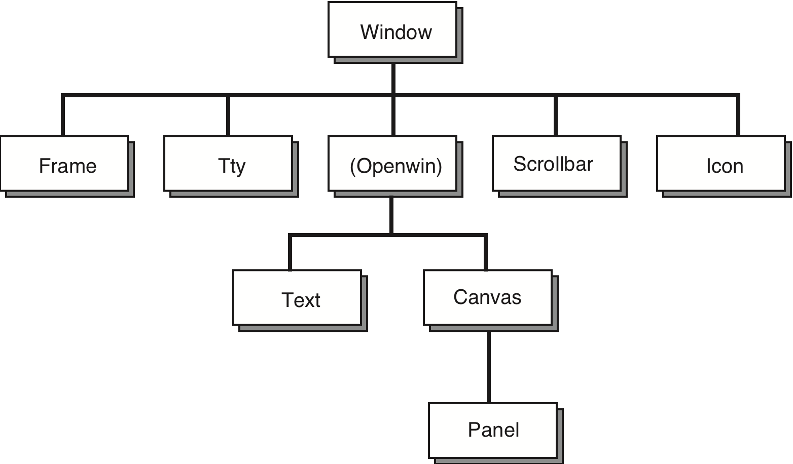
Figure 8.19 The single inheritance class hierarchy of the XView toolkit, after Heller [169], reproduced by permission of O'Reilly and Associates, Inc
We should point out that, though most toolkits are structured in an object-oriented manner, this does not mean that the actual application programming language is object oriented. The example program quit.c is written in the C programming language, which is not an object-oriented language. It is best to think of object orientation as yet another programming paradigm, which structures the way the programmer attacks the programming task without mandating a particular syntax or semantics for the programming language.
The programmer can tailor the behavior and appearance of an interaction object by setting the values of various instance attributes. These attributes must be set before the application program is compiled. In addition, some windowing systems allow various attributes of interaction objects to be altered without necessitating recompilation, though they may have to be set before the actual program is run. This tailorability is achieved via resources that can be accessed by the application program and change the compiled value of some attributes. For efficiency reasons, this tailorability is often limited to a small set of attributes for any given class.
Worked exercise
Scrolling is an effective means of browsing through a document in a window that is too small to show the whole document. Compare the different interactive behavior of the following two interaction objects to implement scrolling:
1. A scrollbar is attached to the side of the window with arrows at the top and bottom. When the mouse is positioned over the arrow at the top of the screen (which points up), the window frame is moved upwards to reveal a part of the document above/before what is currently viewed. When the bottom arrow is selected, the frame moves down to reveal the document below/after the current view.
2. The document is contained in a textual interaction object. Pressing the mouse button in the text object allows you to drag the document within the window boundaries. You drag up to browse down in the document and you drag down to browse up.
The difference between the two situations can be characterized by noticing that, in the first case, the user is actually manipulating the window (moving it up or down to reveal the contents of the document), whereas, in the second case, the user is manipulating the document (pushing it up or down to reveal its contents through the windows). What usability principles would you use to justify one method over the other (also consider the case when you want to scroll from side to side as well as up and down)? What implementation considerations are important?
Answer
There are many usability principles that can be brought to bear on an examination of scrolling principles. For example:
Observability The whole reason why scrolling is used is because there is too much information to present all at once. Providing a means of viewing document contents without changing the contents increases the observability of the system. Scrollbars also increase observability because they help to indicate the wider context of the information which is currently visible, typically by showing where the window of information fits within the whole document. However, observability does not address the particular design options put forth here.
Predictability The value of a scrolling mechanism lies in the user being able to know where a particular scrolling action will lead in the document. The use of arrows on the scrollbar is to help the user predict the effect of the scrolling operation. If an arrow points up, the question is whether that indicates the direction the window is being moved (the first case) or the direction the actual text would have to move (the second case). The empirical question here is: to what object do users associate the arrow – the text or the text window? The arrow of the scrollbar is more closely connected to the boundary of a text window, so the more usual interpretation would be to have it indicate the direction of the window movement.
Synthesizability You might think that it does not matter which object the user associates to the arrow. He will just have to learn the mapping and live with it. In this case, how easy is it to learn the mapping, that is can the user synthesize the meaning of the scrolling actions from changes made at the display? Usually, the movement of a box within the scrollbar itself will indicate the result of a scrolling operation.
Familiarity/guessability It would be an interesting experiment to see whether there was a difference in the performance of new users for the different scrolling mechanisms. This might be the subject of a more extended exercise.
Task conformance There are some implementation limitations for these scrolling mechanisms (see below). In light of these limitations, does the particular scrolling task prefer one over the other? In considering this principle, we need to know what kinds of scrolling activity will be necessary. Is the document a long text that will be browsed from end to end, or is it possibly a map or a picture which is only slightly larger than the actual screen so scrolling will only be done in small increments?
Some implementation considerations:
What scroll mechanisms does a toolkit provide? Is it easy to access the two options discussed above within the same toolkit?
In the case of the second scrolling option, are there enough keys on the mouse to allow this operation without interfering with other important mouse operations, such as arbitrarily moving the insertion point or selecting a portion of text or selecting a graphical item?
In the second option, the user places the mouse on a specific location within the window, and gestures to dictate the movement of the underlying document. What kind of behavior is expected when the mouse hits the boundary of the window? Is the scrolling limited in this case to steps bounded in size by the size of the window, so that scrolling between two distant points requires many separate smaller scrolling actions?
S2.5 Architecture and Frameworks
Despite the availability of toolkits and the valuable abstraction they provide programmers, there are still significant hurdles to overcome in the specification, design and implementation of interactive systems. Toolkits provide only a limited range of interaction objects, limiting the kinds of interactive behavior allowed between user and system. Toolkits are expensive to create and are still very difficult to use by non-programmers. Even experienced programmers will have difficulty using them to produce an interface that is predictably usable. There is a need for additional support for programmers in the design and use of toolkits to overcome their deficiencies. Also, none of the programming mechanisms we have discussed so far in this chapter is appropriate for non-expert programmers, so we still have a long way to go towards the goal of opening up interactive system implementation to those whose main concerns are with HCI and not programming.
S2.5.1 Separation and presentation abstraction: Seeheim
Early in the days of user interface programming, it became evident that another level of services were required for interactive system design beyond the toolkit level. This lead to the development of what were then known as user interface management systems, or UIMS for short. Now-a-days other tersm suchThe term UIMS is now less widely used and many of the functions of UIMS are available as part of general IDEs (integrated development environments), such as NetBeans or Eclipse, either built-in or as a plug-in. However, many of the original concerns of UIMS are still important today:
- a conceptual architecture for the structure of an interactive system which concentrates on a separation between application semantics and presentation;
- techniques for implementing a separated application and presentation whilst preserving the intended connection between them;
- support techniques for managing, implementing and evaluating a run-time interactive environment.
A major issue in this area of research is one of separation between the semantics of the application and the interface provided for the user to make use of that semantics. There are many good arguments to support this separation of concerns:
Portability To allow the same application to be used on different systems it is best to consider its development separate from its device-dependent interface.
Reusability Separation increases the likelihood that components can be reused in order to cut development costs.
Multiple interfaces To enhance the interactive flexibility of an application, several different interfaces can be developed to access the same functionality.
Customization The user interface can be customized by both the designer and the user to increase its effectiveness without having to alter the underlying application.
Once we allow for a separation between application and presentation, we must consider how those two partners communicate. This role of communication is referred to as dialog control. Conceptually, this provides us with the three major components of an interactive system: the application, the presentation and the dialog control. In terms of the actual implementation, this separation may not be so clear.
The first acknowledged instance of a development system that supported this application–presentation separation was in 1968 with Newman's Reaction Handler. The term UIMS was coined by Kasik in 1982 [196a] after some preliminary research on how graphical input could be used to broaden the scope of HCI. The first conceptual architecture of what constituted a UIMS was formulated at a workshop in 1985 at Seeheim, Germany [285]. The logical components of a UIMS were identified as:
Presentation The component responsible for the appearance of the interface, including what output and input is available to the user.
Dialog control The component that regulates the communication between the presentation and the application.
Application interface The view of the application semantics that is provided as the interface (sometimes also referred to as functionality).
Figure 8.20 presents a graphical interpretation of the Seeheim model. We have included both application and user in Figure 8.20 to place the UIMS model more in the context of the interactive system (though you could argue that we have not provided enough of that context by mentioning only a single user and a single application). The application and the user are not explicit in the Seeheim model because it was intended only to model the components of a UIMS and not the entire interactive system. From a programmer's perspective, the Seeheim model fits in nicely with the distinction between the classic lexical, syntactic and semantic layers of a computer system, familiar from compiler design.
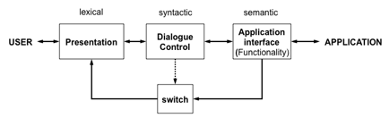
Figure 8.20 The Seeheim model of the logical components of a UIMS
One of the main problems with the Seeheim model is that, whereas it served well as a post hoc rationalization of how a UIMS was built up to 1985, it did not provide any real direction for how future UIMS should be structured. A case in point can be seen in the inclusion of the lowest box in Figure 8.10, which was intended to show that for efficiency reasons it would be possible to bypass an explicit dialog control component so that the application could provide greater application semantic feedback. There is no need for such a box in a conceptual architecture of the logical components. It is there because its creators did not separate logical concerns from implementation concerns.
In graphical and WIMP-based systems the Seeheim components seem restrictive as single entities, and partly in response to this a later workshop developed the Arch–Slinky model [354]. This has more layers than the Seeheim model and, more importantly, recognizes that the mapping of these layers to components of a system may be more fluid than Seeheim suggests.
Semantic feedback
One of the most ill-understood elements of the Seeheim model is the lower box: the bypass or switch. This is there to allow rapid semantic feedback. Examples of semantic feedback include freehand drawing and the highlighting of the trash bin on the Apple Macintosh when a file is dragged over it. As with all notions of levels in interface design, the definition of semantic feedback is not sharp, but it corresponds to those situations where it is impractical or impossible to use dialog-level abstractions to map application structures to screen representations.
The box represents the fact that in such circumstances the application component needs to address the presentation component directly, often to achieve suitable performance. It thus bypasses the dialog component. However, the box has an arrow from the dialog component which represents not a data flow, but control. Although the dialog does not mediate the presentation of information, it does control when and where the application is allowed to access the presentation; hence the alternative name of switch.
S2.5.2 Component models: MVC and PAC
The Seeheim model, and the later Arch–Slinky model,
are monolithic architectures, looking at layers within a system as a
whole. However, as we have already
seen when discussing object-based toolkits, it is often best to build large and
complex interactive systems from smaller components. Several other conceptual
architectures for interactive system development have been proposed to take
advantage of this. One of the earliest was the model–view–controller (MVC) paradigm, used in the
Smalltalk programming environment [233,
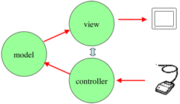
Figure 8.21 The model–view–controller triad in Smalltalk
The basic behavior of models, views and controllers has been embodied in general Smalltalk object classes, which can be inherited by instances and suitably modified. Smalltalk, like many other window toolkits, prescribes its own look and feel on input and output, so the generic view and controller classes (called View and Controller, respectively) do not need much modification after instantiation. Models, on the other hand, are very general because they must be used to portray any possible application semantics. A single model can be associated with several MVC triads, so that the same piece of application semantics can be represented by different input–output techniques. Each view–controller pair is associated to only one model.
The link between Model and View was often maintained by what has since become known as an Observer or Publish–Subscribe pattern. The View registers a callback with the Model and when the Model is updated it invokes the View callback and the View can then update the display accordingly. This means the Control component does not need to explicitly tell the View to update. Furthermore, this makes it possible to have several Views associated with the same Model simultaneously and have all update when the Model changes.
Note that the MVC components do not map directly onto the Seeheim layers for the component. The Model is clearly about the underlying application semantics and the View is about presentation. However, the Controller both manages Dialog and also manages the Presentation-level detail about the input (exactly which keystroke or mouse click is associated with which underlying action). In practice, in graphical interfaces interpretation of mouse actions requires understanding of what is currently displayed on the screen ... which is what the View knows about. This means that View and Controller are often quite closely coupled and come as a pair.
Another multi-agent architecture for interactive systems is the presentation–abstraction–control PAC model suggested by Coutaz [79]. PAC is based on a collection of triads also: with application semantics represented by the abstraction component; input and output combined in one presentation component; and an explicit control component to manage the dialog and correspondence between application and presentation (see Figure 8.22); that is much closer to the Seeheim layers. In addition, the PAC model explicitly deals with the fact that the many individual components of an interface link together to form larger units; in PAC the connection between these is managed by the control component.
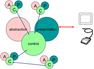
Figure 8.22 The presentation–abstraction–control model of Coutaz
There are three important differences between PAC and MVC. First, PAC groups input and output together, whereas MVC separates them. Secondly, PAC provides an explicit component whose duty it is to see that abstraction and presentation are kept consistent with each other, whereas MVC does not assign this important task to any one component, leaving it to the programmer/designer to determine where that chore resides. Finally, PAC is not linked to any programming environment, though it is certainly conducive to an object-oriented approach. It is probably because of this last difference that PAC could so easily isolate the control component; PAC is more of a conceptual architecture than MVC because it is less implementation dependent.
However, while in many ways PAC represents a cleaner architecture, it has in fact been MVC that has (at least in name) been successful in real use, being used in the Java Swing toolkit [LE02], ASP.NET [MS11b] and many other GUI toolkits and web development frameworks. Looking more closely in many cases what is called "MVC" differs significantly from the original MVC model. In particular the View and Controller are often bundled together.
S2.5.3 Implementation considerations
[[maybe drop this subsection and move to online archive?]]
We have made a point of distinguishing a conceptual architecture from any implementation considerations. It is, however, important to determine how components in a conceptual architecture can be realized. Implementations based on the Seeheim model must determine how the separate components of presentation, dialog controller and application interface are realized. Window systems and toolkits provide the separation between application and presentation. The use of callback procedures in notification-based programming is one way to implement the application interface as a notifier. In the standard X toolkit, these callbacks are directional as it is the duty of the application to register itself with the notifier. In MVC, callback procedures are also used for communication between a view or controller and its associated model, but this time it is the duty of the presentation (the view or controller) to register itself with the application (the model). Communication from the model to either view or controller, or between a view and a controller, occurs by the normal use of method calls used in object-oriented programming. Neither of these provides a means of separately managing the dialog.
Myers has outlined the various implementation techniques used to specify the dialog controller separately. Many of these will be discussed in Chapter 16 where we explicitly deal with dialog notations. Some of the techniques that have been used in dialog modeling in UIMS are listed here.
Menu networks The communication between application and presentation is modeled as a network of menus and submenus. To control the dialog, the programmer must simply encode the levels of menus and the connections between one menu and the next submenu or an action. The menu is used to embody all possible user inputs at any one point in time. Links between menu items and the next displayed menu model the application response to previous input. A menu does not have to be a linear list of textual actions. The menu can be represented as graphical items or buttons that the user can select with a pointing device. Clicking on one button moves the dialog to the next screen of objects. In this way, a system like HyperCard can be considered a menu network.
Grammar notations The dialog between application and presentation can be treated as a grammar of actions and responses, and, therefore, described by means of a formal context-free grammar notation, such as BNF (Backus–Naur form). These are good for describing command-based interfaces, but are not so good for more graphically-based interaction techniques. It is also not clear from a formal grammar what directionality is associated to each event in the grammar; that is, whether an event is initiated by the user or by the application. Therefore, it is difficult to model communication of values across the dialog controller, and that is necessary to maintain any semantic feedback from application to presentation.
State transition diagrams State transition diagrams can be used as a graphical means of expressing dialog. Many variants on state transition diagrams will be discussed in Chapter 16. The difficulty with these notations lies in linking dialog events with corresponding presentation or application events. Also, it is not clear how communication between application and presentation is represented.
Event languages Event languages are similar to grammar notations, except that they can be modified to express directionality and support some semantic feedback. Event languages are good for describing localized input–output behavior in terms of production rules. A production rule is activated when input is received and it results in some output responses. This control of the input–output relationship comes at a price. It is now more difficult to model the overall flow of the dialog.
Declarative languages All of the above techniques (except for menu networks) are poor for describing the correspondence between application and presentation because they are unable to describe effectively how information flows between the two. They only view the dialog as a sequence of events that occur between two communicating partners. A declarative approach concentrates more on describing how presentation and application are related. This relationship can be modeled as a shared database of values that both presentation and application can access. Declarative languages, therefore, describe what should result from the communication between application and presentation, not how it should happen in terms of event sequencing.
Constraints Constraints systems are a special subset of declarative languages. Constraints can be used to make explicit the connection between independent information of the presentation and the application. Implicit in the control component of the PAC model is this notion of constraint between values of the application and values of the presentation. Hill has proposed the abstraction–link–view, or ALV (pronounced 'AL-vee'), which makes the same distinctions as PAC [172]. However, Hill suggests an implementation of the communication between abstraction and view by means of the link component as a collection of two-way constraints between abstraction and view. Constraints embody dependencies between different values that must always be maintained. For instance, an intelligent piggy bank might display the value of its contents; there is the constraint that the value displayed to the outside observer of the piggy bank is the same as the value of money inside it. By using constraints, the link component is described separately from the abstraction and view. Hence, describing the link in terms of constraints is a way of achieving an independent description of the dialog controller.
Graphical specification These techniques allow the dialog specification to be programmed graphically in terms of the presentation language itself. This technique can be referred to as programming by demonstration since the programmer is building up the interaction dialog directly in terms of the actual graphical interaction objects that the user will see, instead of indirectly by means of some textual specification language that must still be linked with the presentation objects. The major advantage of this graphical technique is that it opens up the dialog specification to the non-programmer, which is a very significant contribution.
Ultimately, the programmer would want access to a variety of these techniques in any one UIMS. For example, the Myers Garnet system combines a declarative constraints language with a graphical specification technique. There is an intriguing trend we should note as we proceed away from internal control of dialog in the application itself to external control in an independent dialog component to presentation control in the graphical specification languages. When the dialog is specified internal to the application, then it must know about presentation issues, which make the application less generic. External control is about specifying the dialog independent of the application or presentation. One of the problems with such an independent description is that the intended link between application and presentation is impossible to describe without some information about each, so a good deal of information of each must be represented, which may be both inefficient and cumbersome. Presentation control describes the dialog in the language in terms of the objects the user can see at the interface. Whereas this might provide a simple means of producing a dialog specification and be more amenable to non-programmers, it is also restrictive because the graphical language of a modern workstation is nowhere near as expressive as programming languages.
In summary, components of a UIMS which allow the description of the application separate from the presentation are advantageous from a software engineering perspective, but there has not yet been conclusive proof that they are as desirable in designing for usability. There is currently a struggle between difficult-to-use but powerful techniques for describing both the communication and the correspondence between application and presentation and simple-to-use but limited techniques. Programmers will probably always opt for powerful techniques that provide the most flexibility. Non-programmers will opt for simplicity despite the lack of expressiveness.
S2.5.4 On the web – salami sliced Seeheim
[maybe belongs in web chapter]
The Seeheim. MVC and PAC architectures were all developed in the light of desktop GUI applications. In web applications we can see similar facets but often arranged differently, and in particular the components do not necessarily all sit together in one place.
Given the browser is the bit close to the user it is tempting to think that Seehem presentation layer would live entirely in the browser, with the deeper functionality/semantics at the server end and a separation somewhere in the dialogue component.
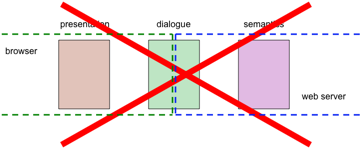
Figure 8.23. Split of Seeheim on Web rarely this simple
In fact, it is not this simple. Instead, we typically see bit of each layer spread between browser and server. At the presentation layer, the actual layout is clearly performed in the browser as is the application of CS style sheets, managing layout of screen areas depending on the window size etc. However, the actual HTML that is delivered to the web page is usually generated in the server either with raw code, or with the help of template engines such as Smarty, or in XML-based web-stacks XSLT to transform XML to HTML.
The dialogue component is similarly split. Some things happen at the browser end. In an old HTML site this is limited to when the user selects links or interacts with web forms; however in a Javascript-rich or Flash-based site the level of interaction can be quite high. However, some of the dialogue is happening at the server side. When the user selects a link to a generated page or presses a form 'submit' button, the back-end server script needs to work out what to do next.
Finally the semantics is largely situated in back-end databases and business logic. However, in rich web applications including those based on AJAX and Web2.0 technology, data may be updated on the page. For example, Google docs spreadsheet is downloaded completely into the web browser and edited there with updates periodically sent to the backend server to keep the two in synchronisation.
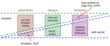
Figure 8.24. More complex split between browser and server
Furthermore if one looks at the scripts generating individual application pages, we will typically see bits of presentation, dialogue and semantics in each. The problem then is that the interaction state becomes fragmented and often developers find it hard to keep track of state spread between server session variables, URL parameters, hidden fields in forms and cookies. There are some MVC-like frameworks for web development, which try to untangle the mess, but the picture is far from solved.
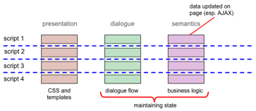
Figure 8.25. Between pages/scripts – salami sliced Seeheim
S2.6 Device Diversity and Plasticity
Devices come in all shapes and sizes from tiny wrist-watch organisers to wall displays. Even on a simple PC screen sizes and window sizes vary as do the kinds of input devices available. Plasticity refers to the ability of an interface to accommodate different kinds of platforms and devices [Co10]. Given the diversity of devices it is an attractive proposition to have a single interface that adapts itself to different devices. However, at some level the kinds of devices vary so much perhaps more radical redesign is called for and for major platforms it is important for applications to 'look native' and to use specific capabilities to the full.
In Section 8.2 we described how window managers do some level of insulation so that an application does not need to know exactly where on the screen it is, what is on top or underneath it and exactly what kind of pointing device is used. The application sees a virtual portion of the screen and a virtual device – mouse track-pad, joystick all appear the same.
The window manager's virtual device abstraction only goes so far; in the end if the application has a screen area of 300 pixels square and an image of 1000 pixels square – does it resize the image, add scroll bars (reducing the area more)? Note there are two separate concerns here:
design – What should happen to the image given the kind of application it is, the nature of the users, the expected task and usage? How should the user interact with it, given again the kind of user, kind of controls available?
implementation – How to achieve the desired interaction style using the events and capabilities of the platform.
These are not independent and the designer has to know what the platform is capable of in selecting an appropriate display strategy and interaction style. However, it is important to realise that these are design decisions, it is easy to forget and let these adaptations, such as behaviour on resizing, become 'accidents' of the design process as a whole. A design decision is made, but is made either during implementation or when the code is running by the default behaviour of the platform.
In this section we look at some of the ways in which platforms and toolkits support this adaptation of interfaces to different device characteristics and also at some of the issues and pitfalls.
S2.6.1 Layout controllers
Most window managers allow users to resize windows. So after you have created a window in your application with a known initial size it may change.
The simplest way to deal with potentially different sized windows is to forbid it! Most window managers allow you to have fixed size windows, for example for tool palettes and dialogue boxes. However, even here whilst the user may not be able to resize the window, the content may not be fixed. An error message may include text of different lengths, in an internationalised interface different languages take more or less letters to say the same things and if users are allowed to resize text then the characters may be bigger or smaller than expected. Even if you ignore all the principles of universal design (Chapter 10) and fix the language, font size etc, when you move your application to a different machine you may find the fonts have slightly different sizes and no longer fit.
Typically these fixed size dialogue boxes work bottom up. The programmer or often the toolkit, calculates the size needed for each element and the overall size of the dialogue box is set to be large enough to contain all the content. Even when the toolkit does this all 'for you' as a programmer, you still have to be careful of extreme cases. The authors have encountered one application where a warning dialogue box can contain text so large that the box is taller than the screen and the bottom of the box extends below the bottom edge of the screen. In particular the 'OK' button is not on screen, so the only way to get rid of the dialogue box is to kill the application.
When a user resizes a window using the window controls, the application gets sent some sort of 'resize' event, in the same way as it gets a mouse click or key press event. The application can then manage this itself in special cases or use toolkit support. This process is typically top down. The overall window size is determined by the user's resizing and then this space is divided up amongst the different elements of the window (buttons, text boxes etc.) and each of these are allocated a size and typically are given 'resize' events themselves.
In both the cases bottom-up due to variable sized content and top-down due to window resizing, not only the sizes of components, but also their locations need to be recalculated to avoid overlaps.
Layout managers are the way in which toolkits help you as an application developer manage this resizing and repositioning of components. Given a screen area and a collection of components (which themselves may contain smaller components), you do not write code that precisely sizes and positions each element. Instead you give minimum and preferred sizes for each component and in some way describe their intended relative positions.
Typically toolkits allow an hierarchy of basic components (button, menu, text box, etc.) contained within 'container' components, which themselves may be contained within other containers. Each container is given a layout manager that specifies how its sub-components are arranged. The precise kinds of available layout varies between platforms and toolkits but typically includes:
vertical – Each component added lies above or below the previous one. Usually you can specify alignment (centred, left or right justified) and, sometimes, extra padding or spacing between elements.
horizontal – Each component added lies beside the previous one. Often you can specify whether the components are provided in left-to-right, right-to-left, or locale default order. This is particularly important in internationalised interfaces where reading order between boxes should reflect reading order of the script.
grid – Table-like layout where you specify a number of rows an columns. Again different forms of alignment are possible.
flow – The components are laid out rather like the words in a text starting a new row or column when they fill the available space. The flow may be horizontal (like English text), or vertical like columns in a newspaper and may be left-to-right or top-to-bottom.
flexible constraints – You specify things like "component A is above component B, component C is to the right of component A" and the toolkit attempts to satisfy all your constraints
fixed – Each component is given a fixed size and location. Of course if a fixed layout is used the programmer must take care of varying sized content. However, you may choose to use this if you are presenting a collection of fixed size images. If a fixed layout is used within a resizable window it must either be a small element amongst other resizable components, or be contained within a scrollable sub-region.
Because of the container hierarchy it is possible to nest kinds of layout to achieve different effects. For example a horizontally laid out button bar may be put within a vertical layout below a text area. Figure 8.26 shows Java AWT/Swing code doing this and Figure 8.27 the output it produces. Note the buttons are given a FlowLayout, which orders them out horizontally, but the frame containing the text and buttons is given a BoxLayout with a PAGE_AXIS option, which lays them out vertically.
JFrame frame = new JFrame("Layout Example");
frame.setDefaultCloseOperation(JFrame.EXIT_ON_CLOSE);
JPanel buttons = new JPanel();
buttons.setLayout(new FlowLayout());
buttons.add(new JButton("Load"));
buttons.add(new JButton("Save"));
frame.getContentPane().setLayout(
     new BoxLayout(frame.getContentPane(), BoxLayout.PAGE_AXIS));
frame.getContentPane().add(new JTextPane());
frame.getContentPane().add(buttons);
frame.pack();
frame.setVisible(true);
Figure 8.26 Code using Java AWT/Swing layout managers
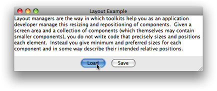
Figure 8.27 Window produced by code in Figure 8.26
S2.6.2 Pagination
When moving from a PC-sized screen to a mobile phone or PDA interface it is typically not possible to simply resize and reorder the elements of a screen. Instead the screen needs to be split into a number of pages with fewer things on each. When this process is carried out automatically it is called pagination as it is rather like splitting the words of a text into pages of a book.
In text there are better and worse ways to split the text. You try to avoid widows and orphans – single lines from a paragraph at the top or bottom or a page, and try to make sure that a heading does not get separated from the first paragraph of the section. Similarly on a screen there are groups of items that are closely related and should stay together when the screen is split up.
If you do this redesign by hand you may not explicitly think about these things, you just do it. However, when the process is automatic you need to specify explicitly what these groups are.
Extensions to standard HTML mark-up have been proposed to enable this for web content [SZ03]. Sections of a document can be marked as groups in a hierarchical fashion and extra information such as running headers provided. The pagination algorithm combines this explicit mark-up with fixed rules (such as header goes with succeeding content) to automatically split up the page. When the document is viewed on a PC it is rendered as a single scrolling page, but on a PDA or phone the pagination algorithm breaks up the original document and adds previous–next elements to allow the user to navigate between the sub-pages of what would normally be considered a single web 'page'.
Particularly difficult to manage are forms where data has to be collected from the various sub-pages and passed as a single package to the application. When the user navigates between sub-pages the data must be retained and presented for editing and care has to be taken with validation to avoid situations where the user cannot navigate because of partially completed information.
While this kind of mark-up is sufficient for many applications it has limits. For example a search engine may provide 10 results per page with its own previous–next buttons. If this is then paginate for a mobile device into, say, 4 pages containing 3, 3, 3 and 1 results respectively. The user is presented with a confusing navigation within navigation. In some case this can be managed by creating a single 'super' page with all the search results and leave pagination entirely to the algorithm. However, often the set of all results is enormous (139,000 results for 'pagination algorithm' in Google!) and are created on demand not all at once.
In other applications too the designer may want to radically change the aspects of the interaction depending on the device capabilities, for example not bothering to show certain fields when entering information on a mobile device. It is this important that information about the destination device capabilities gets through to the application. For example, letting the search engine know that only 3 items can be shown at once and thus letting it paginate appropriately. Unfortunately it is often harder to create a flexible framework than it is to either do nothing (and let the device scroll or zoom) or take over pagination completely and so this kind of passing of information upstream to the application is not well supported.
S2.6.3 Deeper plasticity
Some systems, still at a research stage take the idea of plasticity further and have richer models of the content of the application and even the potential tasks of the user in order to effectively generate interfaces on the fly depending on the particular device and possibly also other known context such as the location, whether the user is moving or stationary (which may effect optimum font size).
One example is UsiXML [LV04,
Final User Interface (FUI) – The actual interface running on a particular platform and language with platform-specific widgets.
Concrete User Interface (CUI)– Here an HTML button (<input type="submit"/>), or a Java Swing JButton are reduced to a generic "Graphical 2D push button".
Abstract User Interface (AUI) – The interface is now abstracted in a modality independent way as 'abstract interaction objects' (AIO); so that a "control AIO" may be a 2D button on screen, or a physical button on the device. Also relationships between AIOs are defined in terms of spatial and temporal constraints, but not precise layout.
Domain/Task Concepts – At this level the interface itself is all but forgotten instead the focus is on what is wanted; for example "load a file" which then at a more concrete may be rendered as a button launching a file selection dialog.
This framework has been used to look at some of the deeper pagination issues noted above, by looking at the underlying task structure [FM06]. However, the adaptations can go far further, for example shifting modality to a speech interface.
Just as with simple pagination, deeper plasticity is not without its problems. While automatic generation may often produce 'good enough' interfaces for unusual situations or as defaults for later amendment, it is rarely going to produce beautiful or optimal interfaces. In simple cases these good enough interfaces may be all that is required. For example, the Ruby on Rails web development framework requires only a specification of a data object and then produces both the database tables and programming classes and in addition a whole web interface for data entry and editing [RG08]. Although one might have produced much more customised forms, the likelihood is that the automatically generated forms are very similar to what would have bee produced for basic system administration tasks. Furthermore, the automatically generated interface is more likely to be complete and correct, covering all the fields with appropriate validation.
In more complex cases the designer may want to create completely novel widgets or complete parts of the interface. A measure of the quality of any development framework with automatic interface generation is the extent to which it is possible to modify the default behaviour through hints, customisation or plug-ins.
We can use the Seeheim model to understand these different forms of plasticity (Figure 8.28):
layout managers – These are operating purely at the presentation layer. The application manages the dialogue and application semantics entirely and the toolkit merely 'helps' with the fine details of screen layout.
pagination – Whilst form an application developers view this can be regarded as still more 'detail's' of presentation, form the user's viewpoint extra dialogue layer features have been added: previous–next navigation, form validation, etc.
deeper plasticity – These are based on models of the application itself and thus involve the specification of application semantics to be passed to the plasticity adaptation engine.
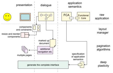
Figure 8.28 Different levels of plasticity
S2.6.4 Platform independence and UI description
In some applications there is a single dedicated platform, for example where software is being developed for custom hardware or where a company has a rigid PC purchasing policy. However, often we need to develop software that runs on a variety of platforms: Linux, Mac OS, Windows and perhaps for a mobile applications Android, iOS or WindowsCE.
Each of these platforms has native APIs giving the finest level of control over the system and interface. If you have sufficient budget you may develop for each platform specifically. However, if you are developing cross-platform it is often sensible to deliberately use only common features to create a single application that runs on any platform. There have been many cross platform user interface toolkits developed for exactly this purpose, usually related to a single programming language, for example the Tcl/Tk toolkit and Java AWT and Swing. Indeed, as well as being the language of the web, one of the early promotion jingles for Java was "write once, run anywhere".
Platform independent toolkits typically include widgets for the standard WIMP elements (menus, windows, text areas, buttons, etc.) and take care of mapping these into the native windowing API. Some of these toolkits operate on a very low level simply accepting low-level mouse events and treating the native window as a plain bitmap. Doing this means that the same application appears identical no matter where it runs. However, this means that it does not look as if it 'belongs' on the native platform. Other toolkits map their internal widgets onto the corresponding Widget on the native platform so that a menu on a Mac OS looks like a Mac OS menu, but on Windows looks like a Windows menu.
In Java the early AWT classes adopt the second model, mapping Java classes to corresponding native 'peer' components, whilst the later Swing classes use the first model accessing the window bitmap directly. Java calls the former heavyweight components and the latter lightweight components. In order to allow Swing interfaces to look more native Java allows a pluggable 'look and feel' – however the components whilst looking more like the native ones are not really native and therefore may behave differently even though they look the same.
The use of native components is usually more efficient and provides faster user interaction as well as producing a more 'native' feeling application. However, they are less extensible limited to what is available in all platforms. In addition, the sometimes odd interactions between apparently similar event and widget models on different platforms can cause problems for applications when they are ported, obviating the advantages of the whole platform-independent toolkit. For example, in early version of Java AWT on the Windows platform it was possible to get two mouse down events without an intervening mouse up!
Various user interface description notations have been
developed in order to describe interface layout in platform and device
independent fashion. Like the
toolkits these usually include standard widgets and ways of specifying layout,
but using a special syntax instead of programming language functions, classes
and code. Recently such languages tend to be based around XML notably XUL (XML
User Interface Language, pronounced "zool") used to create Mozilla
plug-ins and stand-alone applications [Ma05,
<?xml version="1.0"?>
<?xml-stylesheet href="chrome://global/skin/xul.css" type="text/css"?>
<!DOCTYPE window>
<window id="main-window" xmlns:html="http://www.w3.org/1999/xhtml"
         xmlns="http://www.mozilla.org/keymaster/get...re.is.only.xul">
   <menubar>
       <menu label="File">
       <menupopup>
         <menuitem label="Hello World!"
                    onclick="alert('Hello world!\n');"/>
       </menupopup>
       </menu>
   </menubar>
  <html:iframe id="content-frame" src="contentframe.html" flex="100%"/>
</window>
Figure 8.29 XUL code example from [Ma05]
S2.6.5 Harnessing platform specific features
Each platform has its own specific features that you may want to use in your application: for example, to have an icon in the Windows tool tray or to have a Mac OS application work with Apple Automator. Where possible it is still desirable to maintain a core of the interface that is platform independent, but still allow platform specific features.
In the case of a platform-independent toolkit, the application 'knows' that it has, for example, a window with a menu and text area on it. It does not know exactly how there appear, but the control and overall flow of the interaction – the dialogue – is centred in the application. If the same style of programming is used with platform-specific features then the application needs to either have multiple variants in its central user interface code, or have a series of conditionals throughout the code of the form:
if ( Windows platform) {
	do tool tray code
} else if ( MacOS platform ) {
	do automator stuff
} ...
If the platform specific features are limited this may be acceptable, but if not it is clear that this style will soon become unwieldy. The solution is to maintain a much stronger separation between the application core functionality and user interface (Seeheim style). This will typically involve creating a clear API to the functional core and then writing both the platform independent UI and the platform specific parts to access this (see figure PSPS). That is the core does not know about the user interface but the user interface does know about the core.
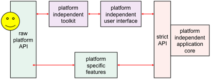
Figure 8.30 Integrating platform specific features
It is important though that the application core API supplies callbacks for changes, just like the Model in the MVC framework so that, for example, when a setting is changed through a tool tray menu this is reflected in the main interface. That is in Figure 8.30, the arrows from the core's API to the user interface elements to the left involve both returning information directly as the result of method/function calls and also notification when aspects of the application state changes.
An additional strength of this form of loosely coupled architecture is that one can start with a platform independent user interface and gradually add platform specific features, potentially even deciding at some point to write completely native user interfaces for very particular platforms.
With the rise of web services there are a growing number of small desktop applications that are simply thin interfaces over predominantly web applications. Many of the Mac OS Dashboard widgets are of this kind. This is similar to the architecture in Figure 8.30, except instead of an API we have a network protocol between user interface and application core. This same style of architecture can be used on purely client-based applications with a stand-alone application running on a user's own machine that communicates with the locally running user interface through network protocols, but all on the same machine. This sounds like a heavy overhead, but in fact is the way many database servers work and is managed reasonably efficiently by most operating systems. The network interaction may be used just for the connection to platform specific features (lower part of Figure 8.30), or may be used to separate all of the UI. This radical separation can be especially valuable where there are potential difficult interactions with native code (e.g. Windows threads and Java threads) or where it is useful to develop the platform specific features in a different language to the core application.
S2.7 The Future: Physical Devices and End-User Programming
This chapter has been mainly focused on GUI-based interface programming. Web-based and mobile interfaces have been mentioned, but they still largely follow the GUI-style. However, there are many specialised areas, for example, visualisation, virtual reality and games (see Chapter 20), which require different styles of programming. Perhaps most extreme are devices where the physical form is as critical as the digital aspects. Apple consumer products such as the iPad epitomise the close connection between physical form and user experience, but this equally true in prosaic devices such as a washing machine, or on the horizon technologies such as ubiquitous computing (see Chapter 21).
We have also taken the programmer as the primary focus. However, over the years there have been tools aimed at less technical users wishing to produce interactive systems for themselves including HyperCard, Visual Basic, Flash and web authoring environments such as Dreamweaver. These typically combine 'screen painting' with the ability to add behaviours to elements. With the rise of mashup culture on the web (see Chapter 25) (near) end-user programming is becoming more mainstream. However, still there are major hurdles in moving from simple predefined behaviours to more general coding.
S2.8 Summary
In this chapter, we have focused on the programming support tools that are available for implementing interactive systems. We began with a description of windowing systems, which are the foundation of modern WIMP interfaces. Window systems provide only the crudest level of abstraction for the programmer, allowing her to gain device independence and multiple application control. They do not, however, provide a means of separating the control of presentation and application dialog. We described a number of ways in which displays are managed and two paradigms for event processing in interactive programming. We saw how the different event paradigms relate to two means of controlling that dialog – either internal to the application by means of a read–evaluation loop or external to the application by means of notification-based programming. We also saw how event processing may require asynchronous code or threads to manage long lasting computation. Toolkits used with particular windowing systems add another level of abstraction by combining input and output behaviors to provide the programmer with access to interaction objects from which to build the components of the interactive system. Toolkits are amenable to external dialog control by means of callback procedures within the application. Architectural styles provide yet another level of abstraction in interactive system development. The early Seeheim model has been very influential as a conceptual model separating presentation, dialog and underlying functionality. For implementation more component-based architectures are needed such as MVC and PAC, with variants of MVC being particularly heavily used in toolkits and frameworks including Java Swing. We saw that the mapping of these architectures onto web-based interfaces was not a simple layering with presentation in the browser, but included aspects of all three levels in Seeheim. Finally we looked at different ways in which interfaces can provide 'plasticity' adapting to different device characteristics in particular screen size.
Exercises
Exercise 8.1
In contrasting the read–evaluation loop and the notification-based paradigm for interactive programs, construction of a pre-emptive dialog was discussed. How would a programmer describe a pre-emptive dialog by purely graphical means? (Hint: Refer to the discussion in Section 8.5 concerning the shift from external and independent dialog management to presentation control of the dialog.)
Exercise 8.2
Look ahead to the example of the state transition diagram for font characteristics presented in Chapter 16 (Section 16.3.3). Compare different interaction objects that could implement this kind of dialog. Use examples from existing toolkits (pull-down menus or dialog boxes) or create a novel interaction object.
Exercise 8.3
This exercise is based on the nuclear reactor scenario on the book website at: /e3/scenario/nuclear/
(a) In the Seeheim model: treating the Application Interface model and Application together, there are three main layers:
(i) presentation/lexical
(ii) dialog/syntactic
(iii) application/semantic.
For each of these three layers, list at least two different items of the description of the nuclear reactor control panel that are relevant to the level (that is, at least six items in total, two for each level).
(b) There are no items in the description that relate to the switch (rapid feedback) part of the Seeheim model. Why do you think this is?
Exercise 8.4
A user has a word processor and a drawing package open. The word processor's window is uppermost. The user then clicks on the drawing window (see figure below). The drawing window pops to the front.
Describe in detail the things that the window manager and applications perform during the processing of the mouse click in the above scenario. Explain any assumptions you make about the kind of window manager or application toolkits that are being used.
Exercise 8.5
A designer described the following interface for a save operation.
The users initially see a screen with a box where they can type the file name (see Screen 1). The screen also has a 'list' button that they can use to obtain a listing of all the files in the current directory (folder). This list appears in a different window. When the user clicks the save button, the system presents a dialog box to ask the user to confirm the save (see Screen 2).
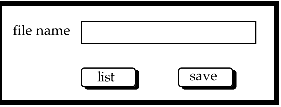
screen 1
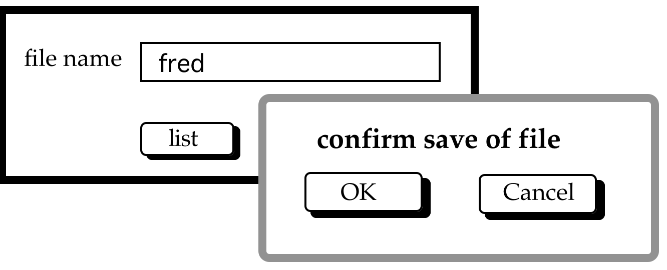
screen 2
Two programmers independently coded the interface using two different window managers. Programmer A used an event-loop style of program whereas programmer B used a notifier (callback) style.
(a) Sketch out the general structure of each program.
(b) Highlight any potential interface problems you expect from each programmer and how they could attempt to correct them.
Exercise 8.6
The code below produces the following interface.

When you press the "=" button, the sum of the two numbers (in this case 35 and 23) is put into the result area (below the "=").
Note some lines of code are omitted as not relevant to the exercises. Java comments indicate where code has been removed.
 1  // various imports
 2
 3  public class AddThem2 implements ActionListener {
 4      // code to declare buttons, etc. including:
 5      private JButton equalsButton;
 6
 7      public AddThem2() {
 8          // lots of code to create panels, buttons etc.
 9          equalsButton = new JButton("=");
10          equalsButton.addActionListener(this);
11          // and more, adding equalsButton to panel, etc.
12      }
13      public void doEquals() {
14          sumField.setText("Just thinking");
15          String num1str = num1Field.getText();
16          String num2str = num2Field.getText();
17          int num1 = Integer.parseInt(num1str);
18          int num2 = Integer.parseInt(num2str);
19          int sum = num1+num2;  //**** REAL WORK HERE ****
20          String sumStr = "" + sum;
21          sumField.setText(sumStr);
22      }
23       public void actionPerformed(ActionEvent e) {
24           if ( e.getSource() == equalsButton ) {
25               doEquals();
26           }
27       }
28   }
- The code at line 14 says: sumField.setText("Just thinking"); This is clearly intended to put the words "Just thinking" in the answer box while the answer is being computed. Would you expect to see the words when you press the "=" buttons? Explain your answer.
- Using a diagram if helpful, describe the main stages that occur between when the user clicks the '=' button until the result is shown. Describe clearly when the different parts of code execute and what the user would see at any critical step.
- Assume the code is modified to do a substantial and time-consuming computation at line 19. The developer notices it appears to 'hang' and does not display the "just thinking" message at line 14. Explain why this happens.
- How might you make this work as planned, that is make the words "Just thinking" appear when the computation at line 19 were more complicated. Note you do not need to write the code, just describe what you would do.
- Assume again the time-consuming computation is being performed at line 19, but the code has not been modified following your suggestions. Assume also that the window manager you are using adopts a non-retained buffering strategy.
While the computation is proceeding the user gets bored and pops up a web browser, which partially obscures the 'Add Them' window. After a while the user closes the browser window, but the computation has still not yet completed. Explain what will the user see and why? - How would the answer to part (v) differ if the window manager used a retained or buffered strategy.
- No it would not appear because the sum would appear too quickly (and furthermore the paint thread does not start to work while the UI thread is busy).
- Basically bookwork from the event section.
- Even though there is now time, paint is only called when the UI thread is not busy.
- Add a separate thread to do the computation that is triggered by the UI thread, but goes on doing the computation 'in the background' and then updates variables when the computation is complete.
- The obscured part of the 'Add Them' window would not update and hence would show part of the browser window that had covered it, or possibly have been blanked (but not refilled) by the WM.
- Both retained and buffered strategies would lead to the window being fully repainted.
Recommended reading
Dan Olsen. 2009. Building Interactive Systems: Principles for Human-Computer Interaction (1st ed.). Course Technology Press, Boston, MA, United States.
Olsen is one of the major figures in this area. This book covers in detail issues introduced in this chapter including event management, widgets, layout and MVC, plus much more from internationalisation to digital ink.
Brad Myers, Scott E. Hudson, and Randy Pausch. 2000. Past, present, and future of user interface software tools. ACM Trans. Comput.-Hum. Interact. 7, 1 (March 2000), 3-28. DOI=10.1145/344949.344959 http://doi.acm.org/10.1145/344949.344959
This paper reviews both successful interface construction tools and also classes of tools that were (and maybe still do) have promise, but for whatever reason have not made it to market; for example, UIMS.
Harold Thimbleby, Press On: Principles of Interaction Programming. MIT Press, 2007 ISBN:0-262-20170-4
This book bridges prototyping, formal analysis and design. It takes a principled approach, including methods for analysing of state-transition representations of user interfaces, lightly sprinkled with JavaScript code.
Scott R. Klemmer and James A. Landay, Toolkit Support for Integrating Physical and Digital Interactions. Human–Computer Interaction, 2009, Volume 24, pp. 315–366. DOI: 10.1080/07370020902990428
This paper is partly presenting the authors' own physical interaction toolkit, Papier-Mâché. However, it also contains an analytic review of a large number of systems that link physical and digital interaction.
Fabio Paternò and Carmen Santoro, Markup Languages in HCI. Chapter 26 in Constantine Stephanidis (ed), The Universal Access Handbook, CRC Press, 2009, pp. 409–428 , ISBN: 0805862803
Describes a variety of XML-based languages used to described user interfaces, and the underlying principles behind their use.
Extra Refs
Ap10 Apple Inc. (2010) NSWindow Class. Mac Developer Library. http://developer.apple.com/library/mac/#documentation/Cocoa/Reference/ApplicationKit/Classes/NSWindow_Class/Reference/Reference.html#//apple_ref/c/tdef/NSBackingStoreType
Bo11 Peter Bojanic. The Joy of XUL. Mozzilla Developer Network (accessed March 2011) https://developer.mozilla.org/en/the_joy_of_xul
Co10 Joëlle Coutaz. User Interface Plasticity: Model Driven Engineering to the Limit! In ACM, Engineering Interactive Computing Systems (EICS 2010). pages 1-8. 2010.
Ga05 Garrett, J.J. (18 February 2005). Ajax: A New Approach to Web Applications. Adaptive Path. Retrieved 29 Nov 2007. http://www.adaptivepath.com/ideas/ajax-new-approach-web-applications
Ma05 Daniel Matejka. Introduction to XUL. Mozzilla Developer Network (dated January 31, 2005; accessed March 2011) https://developer.mozilla.org/en/introduction_to_xul
MS11 Microsoft 2011. XAML Overview (WPF). Microsoft (accessed March 2011) http://msdn.microsoft.com/en-us/library/ms752059.aspx#xaml_files
MS11b Microsoft 2011. Web Presentation Patterns. http://msdn.microsoft.com/en-us/library/ff650511.aspx
SZ03 Axel Spriestersbach, Thomas Ziegert, Guido Grassel, Michael Wasmund, and Gabriel Dermler. Flexible pagination and layouting for device independent authoring. In WWW2003 Emerging Applications for Wireless and Mobile Access Workshop, 2003.
FM06 Murielle Florins, Francisco Montero Simarro, Jean Vanderdonckt, and Benjamin Michotte. 2006. Splitting rules for graceful degradation of user interfaces. In Proceedings of the working conference on Advanced visual interfaces (AVI '06). ACM, New York, NY, USA, 59-66. DOI=10.1145/1133265.1133276
LV04 Limbourg, Q., Vanderdonckt, J., Michotte, B., Bouillon, L. and Lopez, V. UsiXML: a language supporting multi-path development of user interfaces. In Proc. of EHCI-DSVIS' 2004 (Hamburg, July 11-13, 2004). Lecture Notes in Computer Science, Vol. 3425, Springer-Verlag, Berlin, 2005, 200-220.
UX11 UsiXML - Home of the USer Interface eXtensible Markup Language. (accessed March 2011) http://www.usixml.org/
RG08 Getting Started with Rails. RailsGuides. (first version Sept 2008, accessed March 2011) http://guides.rubyonrails.org/getting_started.html
LE02 Marc Loy, Robert Eckstein, David Wood, James Elliott. Java Swing, Second Edition, O'Reilly, 2002, ISBN 0-596-00408-7